
Hydraulic high-speed water-hammering punch press

A punching machine and hydraulic technology, which is applied in the direction of abrasive jetting machine tools, used abrasive processing devices, abrasives, etc., can solve the problems of high noise, poor cooling effect of hydraulic oil, complicated operation, etc., to achieve effective cooling and reduce punching Hole Noise Effect

Active Publication Date: 2020-04-10
盐城青松机械制造有限公司
View PDF7 Cites 0 Cited by
  • Summary
  • Abstract
  • Description
  • Claims
  • Application Information

AI Technical Summary

Problems solved by technology

[0002] Hydraulic high-speed punching machine is a kind of punching process that can realize small-thickness metal. It has high efficiency and high processing accuracy. At present, the common hydraulic high-speed punching machine is composed of the following parts: hydraulic cylinder actuator, stamping die , hydraulic pump combination and control part, but this kind of punching machine has the following disadvantages: 1. The punching machine uses the mold to directly contact the metal to be processed, and the material removal process is realized through the assistance of the mold. Clumsy. 2. A single mold for mechanical punching can only process a single hole. If you need to process other holes, you need to replace the tool and mold. The operation is complicated. 3. The cooling method of hydraulic oil is usually water cooling, but the contact between water cooling and high temperature hydraulic oil The area is small, which leads to poor cooling effect of the hydraulic oil, so the present invention provides a hydraulic high-speed water hammer punching machine

Method used


Image

  • Hydraulic high-speed water-hammering punch press
  • Hydraulic high-speed water-hammering punch press
  • Hydraulic high-speed water-hammering punch press

Examples


Embodiment approach

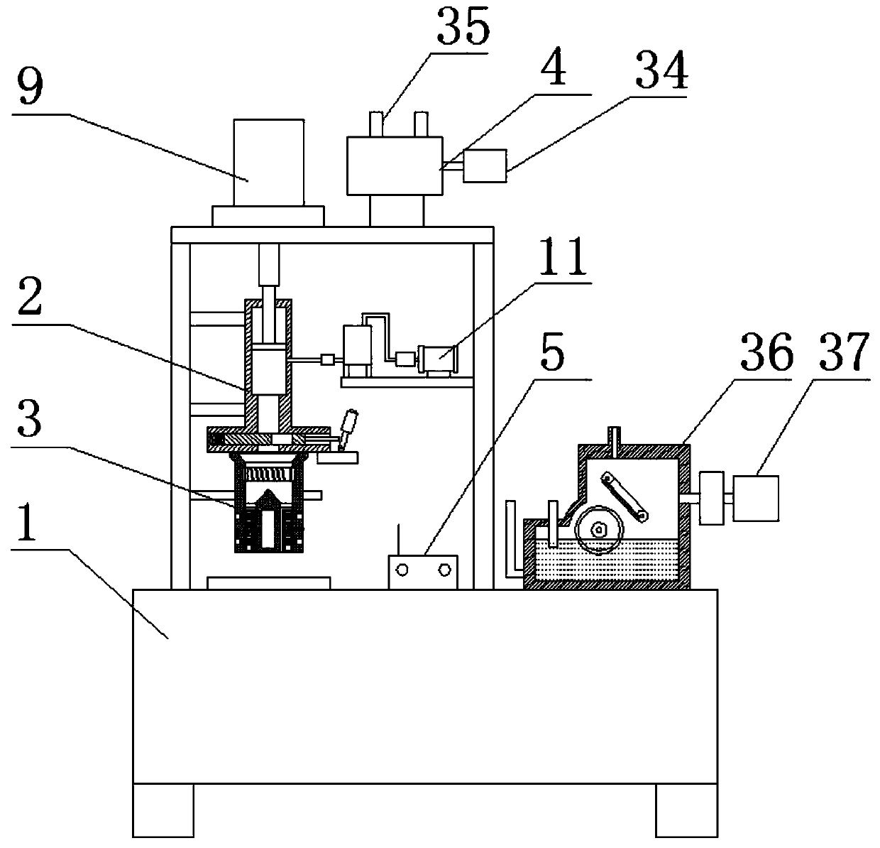
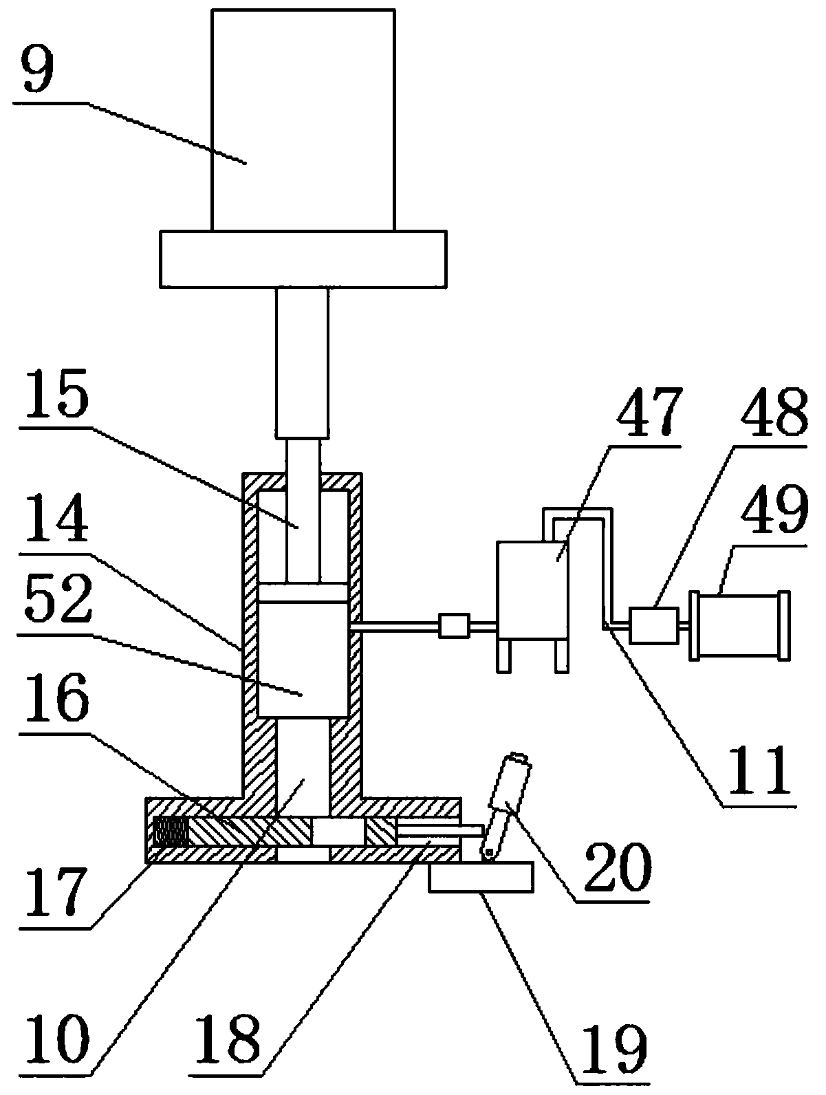
[0027]As a preferred embodiment of the present invention, the water supply system 11 includes a water tank 47, a water pump 48 and a water supply motor 49, the water pump 48 is arranged at one end of the water supply motor 49, the water tank 47 is connected to the water pump 48 through a pipeline, The bottom of the water tank 47 is provided with a check valve.

[0028] As a preferred embodiment of the present invention, the electromagnet 33 is provided with an electromagnetic winding.

[0029] As a preferred embodiment of the present invention, one end of the driving roller 43 is provided with a driving pulley 51, and one end of the driven roller 44 is provided with a driven pulley 50, and the driving pulley 51 passes through a belt and a driven pulley. The pulley 50 is connected.

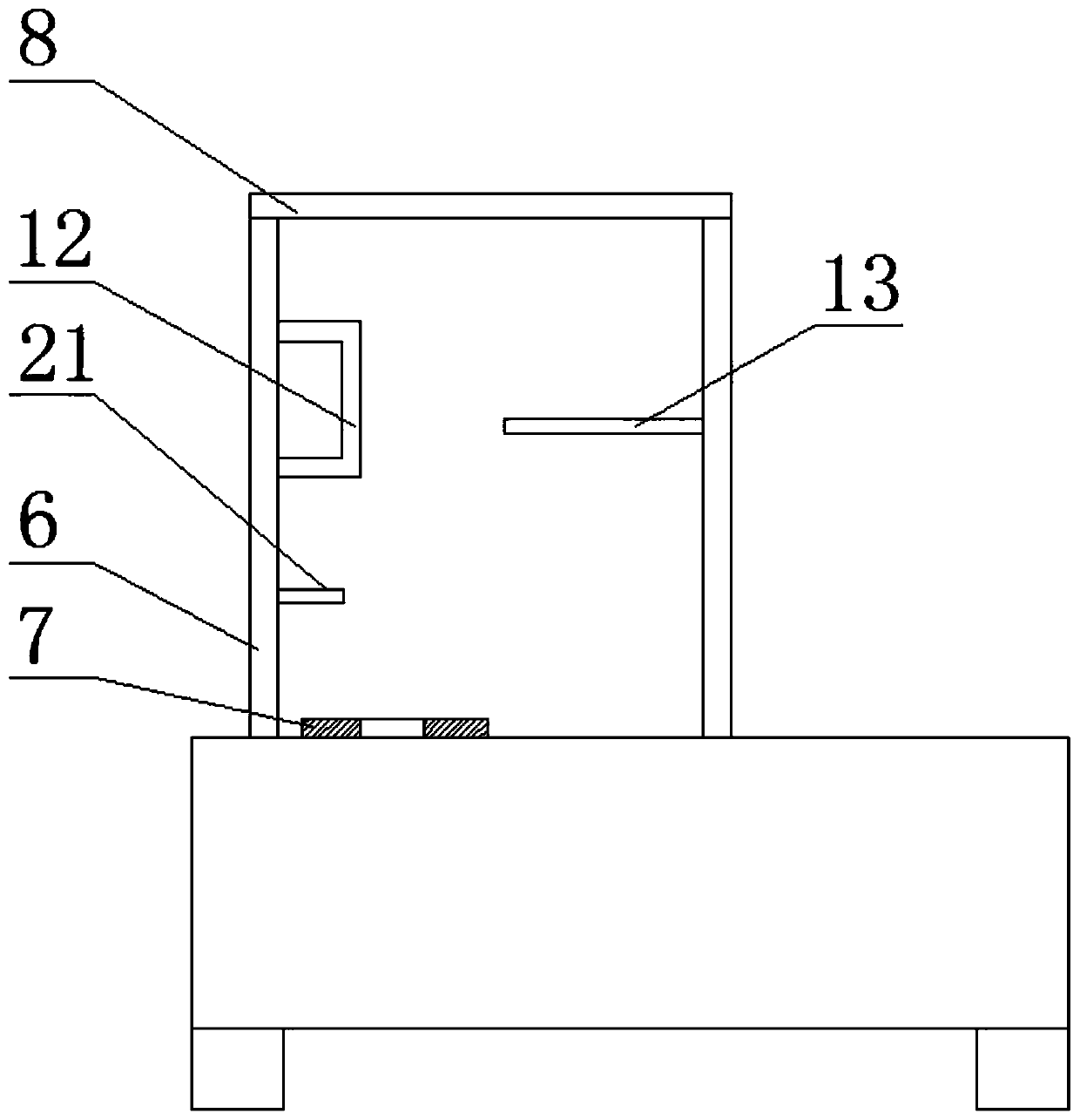
[0030] As a preferred embodiment of the present invention, the punching station 7 corresponds to the water jacket 22 .

[0031] As a preferred embodiment of the present invention, the oil tank bo...


PUM


Abstract

The invention discloses a hydraulic high-speed water-hammering punch press. The hydraulic high-speed water-hammering punch press comprises a punch rack, a hydraulic water washing unit, a pore diametercontrol unit, a cooling device and a control electrical box, wherein a supporting frame and a punch table are arranged on the punch rack; the top of the supporting frame is equipped with a seat tableboard; the hydraulic water washing unit comprises a pressurizing hydraulic cylinder, a water washing pressurizing cylinder and a water supply system; a positioning sleeve is arranged on the seat table board; the pressurizing hydraulic cylinder is mounted on the seat table board through the positioning sleeve; and one side of the supporting frame is equipped with a washing fixing frame. The hydraulic high-speed water-hammering punch press adopts the pressurizing hydraulic cylinder to indirectly apply pressure to the water washing pressurizing cylinder, so that large oil cylinder pressure is converted into air pressure of the water washing pressurizing cylinder, and therefore, large air pressure instantaneously pushes water flow in the water washing pressurizing cylinder, water flow is sprayed to a to-be-processed object with high-speed impact force, water flow punching replaces conventional mould punching, and punching noises can be reduced; and meanwhile, a mould is not needed for assisting processing.

Description

technical field [0001] The invention relates to the technical field of hydraulic punching, in particular to a hydraulic high-speed water hammer punching machine. Background technique [0002] Hydraulic high-speed punching machine is a kind of punching process that can realize small-thickness metal. It has high efficiency and high processing accuracy. At present, the common hydraulic high-speed punching machine is composed of the following parts: hydraulic cylinder actuator, stamping die , hydraulic pump combination and control part, but this kind of punching machine has the following disadvantages: 1. The punching machine uses the mold to directly contact the metal to be processed, and the material removal process is realized through the assistance of the mold. Clumsy. 2. A single mold for mechanical punching can only process a single hole. If you need to process other holes, you need to replace the tool and mold. The operation is complicated. 3. The cooling method of hydrau...

Claims


Application Information

Patent Timeline
Patent Type & Authority Applications(China)
IPC IPC(8): B24C1/04B24C3/00B24C7/00B24C9/00
CPCB24C1/045B24C3/00B24C7/0015B24C9/00
Inventor 马雪婷
Owner 盐城青松机械制造有限公司
Learn More