Vibration stirring device capable of improving distribution uniformity of cement particles

A particle distribution and vibration stirring technology, which is used in cement mixing devices, clay preparation devices, chemical instruments and methods, etc., can solve problems such as uneven distribution, cement agglomeration, and mixture segregation.

Inactive Publication Date: 2020-04-10
CHINA FIRST METALLURGICAL GROUP
View PDF7 Cites 1 Cited by
  • Summary
  • Abstract
  • Description
  • Claims
  • Application Information

AI Technical Summary

Problems solved by technology

[0002] In all grades of highway pavement projects, the cement-stabilized macadam base is the most widely used. At present, the cement-stabilized macadam base materials at home and abroad generally adopt self-falling or forced mixing technology. The above two methods are actually static mixing. The way of static mixing can easily lead to the uneven distribution of cement lumps and ash lumps in the mixture, resulting in segregation of the mixture. The above defects are caused by early cracks in the cement-stabilized macadam base, and thus induce cracks in the asphalt pavement Therefore, improving the uniformity of cement particle distribution and thus improving the durability of the pavement has become an urgent problem to be solved

Method used


Image

  • Vibration stirring device capable of improving distribution uniformity of cement particles
  • Vibration stirring device capable of improving distribution uniformity of cement particles
  • Vibration stirring device capable of improving distribution uniformity of cement particles

Examples


Embodiment Construction

[0024] The present invention will be further described below in conjunction with the drawings and embodiments.

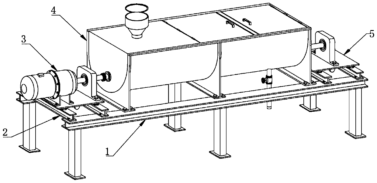
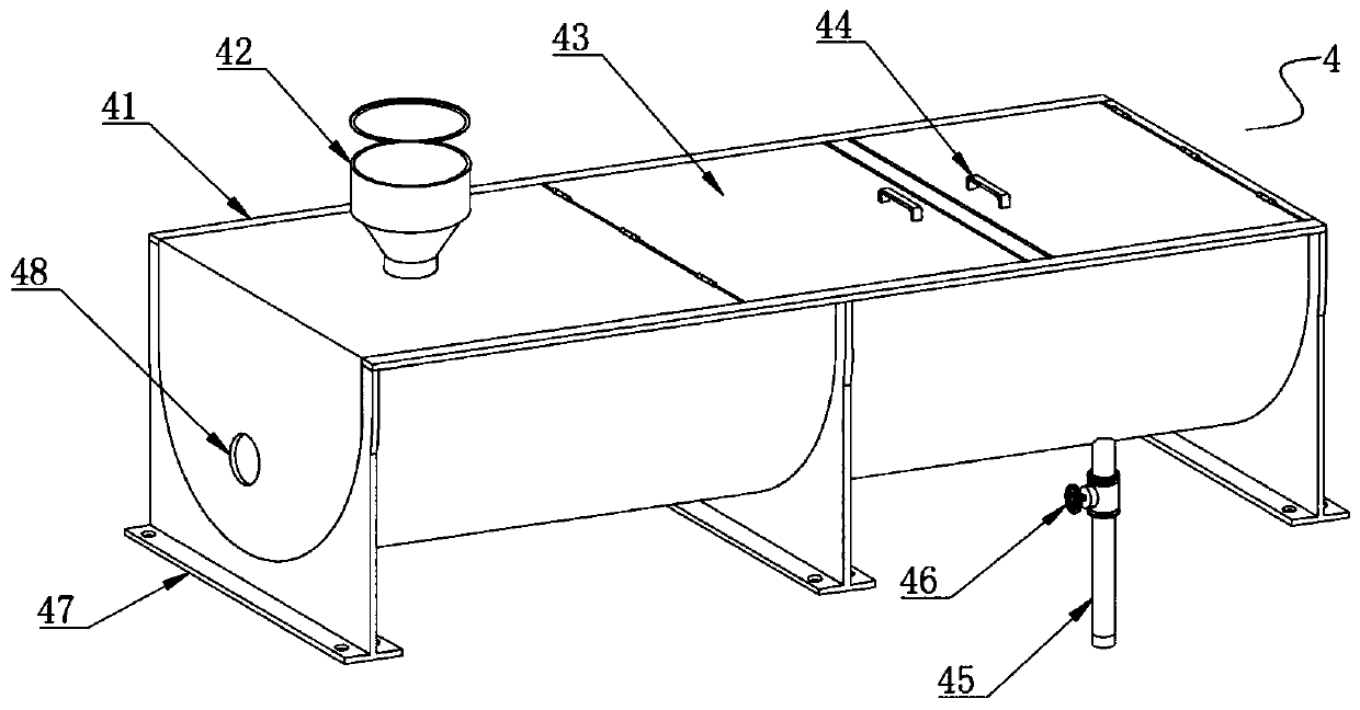
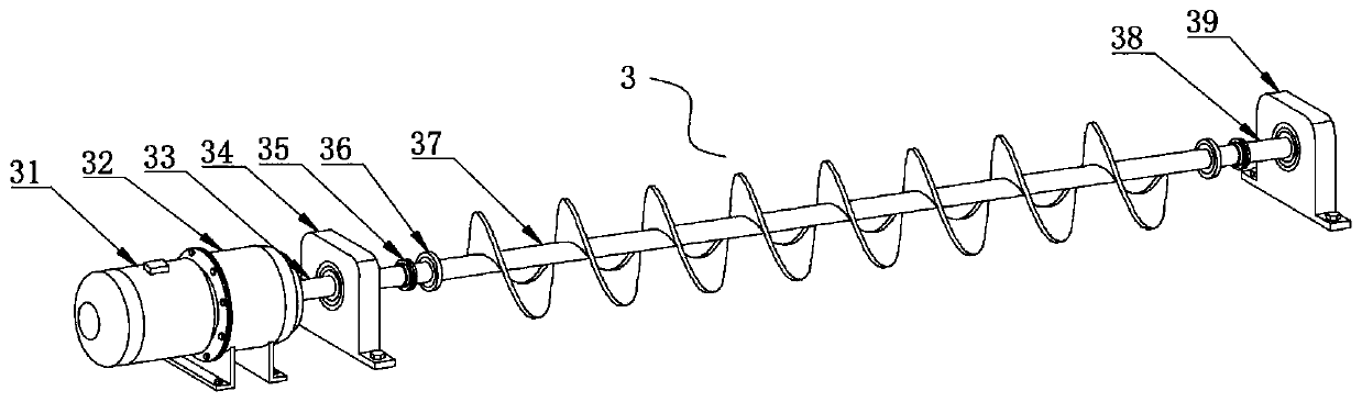
[0025] Such as Figure 1 to Figure 3 As shown, a vibrating stirring device that can improve the uniformity of cement particle distribution includes 4 silos, a first vibrating platform 2 and a second vibrating platform 5 located at both ends of the 4 silos, and a stirring mechanism 3, and the upper part of the silo 4 It is provided with a feed port 42, a discharge port 45 with a valve 46 at the lower part, and shaft holes 48 at both ends. The stirring mechanism 3 includes a stirring shaft 37, a stirring motor 31, a reducer 32, a first bearing seat 34 and In the second bearing seat 39, the stirring shaft 37 is arranged longitudinally in the silo 4 with stirring blades. The two ends of the stirring shaft 37 are matched with the elastic shaft seal 36 to penetrate the corresponding shaft hole 48, and respectively connect with the shaft through the coupling 35. The first ro...


PUM


Abstract

The invention discloses a vibration stirring device capable of improving the distribution uniformity of cement particles. The vibration stirring device capable of improving the distribution uniformityof the cement particles comprises a stock bin, a first vibration platform, a second vibration platform and a stirring mechanism, wherein a charge port is formed in the upper part of the stock bin, adischarge port with a valve is formed in the lower part of the stock bin, and shaft holes are formed in the two ends of the stock bin; the stirring mechanism comprises a stirring shaft, a stirring motor, a speed reducer, a first bearing seat and a second bearing seat; the two ends of the stirring shaft penetrate out of the corresponding shaft holes in a matching manner through elastic shaft seal,and are connected with one end of the first rotary shaft and one end of the second rotary shaft through a shaft coupling separately; the stirring motor, the speed reducer and the first bearing seat are arranged on a vibration surface of the first vibration platform; the stirring motor, the speed reducer and the other end of the first rotary shaft are sequentially connected; the first rotary shaftis supported on the first bearing seat in a matching manner; the second bearing seat is arranged on a vibration surface of the second vibration platform; and the other end of the second rotary shaft is supported on the second bearing seat in a matching manner. The device is capable of crushing cement balls and ash balls in a mixture through vibration, and uniformly distributing the cement balls and the ash balls into the mixture, and simple in structure.

Description

Technical field [0001] The invention belongs to the field of cement processing equipment, and specifically relates to a vibration stirring device capable of improving the uniformity of cement particle distribution. Background technique [0002] In all levels of highway pavement engineering, cement stabilized crushed stone base is the most used. At present, cement stabilized crushed stone base materials at home and abroad generally adopt self-falling or forced mixing technology. The above two methods are actually static mixing. The static mixing method can easily lead to uneven distribution of cement clusters and ash aggregates in the mixture, resulting in mixture segregation. The above-mentioned defects cause early cracks in the cement stabilized crushed stone base and induce cracks in the asphalt pavement. Therefore, improving the uniformity of cement particle distribution and thereby improving the durability of the road surface has become an urgent problem to be solved. Summar...

Claims


Application Information

Patent Timeline
Patent Type & Authority Applications(China)
IPC IPC(8): B28C5/14B28C5/48
CPCB28C5/142B28C5/48
Inventor 闫静安陈云华陈慕平廖红玉孙仕斌鲁丙奎
Owner CHINA FIRST METALLURGICAL GROUP
Why Eureka
Try Eureka