Regenerative braking energy recovery system of hydraulically-driven automobile

A technology of regenerative braking and energy recovery, which is applied in the direction of brakes, braking components, braking transmission devices, etc., can solve the problems of limited remaining space and difficulties, and achieve the effects of reduced transmission structure, low cost and good passability

Pending Publication Date: 2020-04-10
ZHEJIANG UNIV OF TECH
View PDF0 Cites 2 Cited by
  • Summary
  • Abstract
  • Description
  • Claims
  • Application Information

AI Technical Summary

Problems solved by technology

It is more difficult to arrange the hydraulic regenerative braking system on the current internal combustion engine passenger car with compact mechanical structure and little remaining space

Method used


Image

  • Regenerative braking energy recovery system of hydraulically-driven automobile

Examples


Embodiment Construction

[0015] Further illustrate the present invention below in conjunction with accompanying drawing

[0016] Refer to the accompanying drawings in the manual:

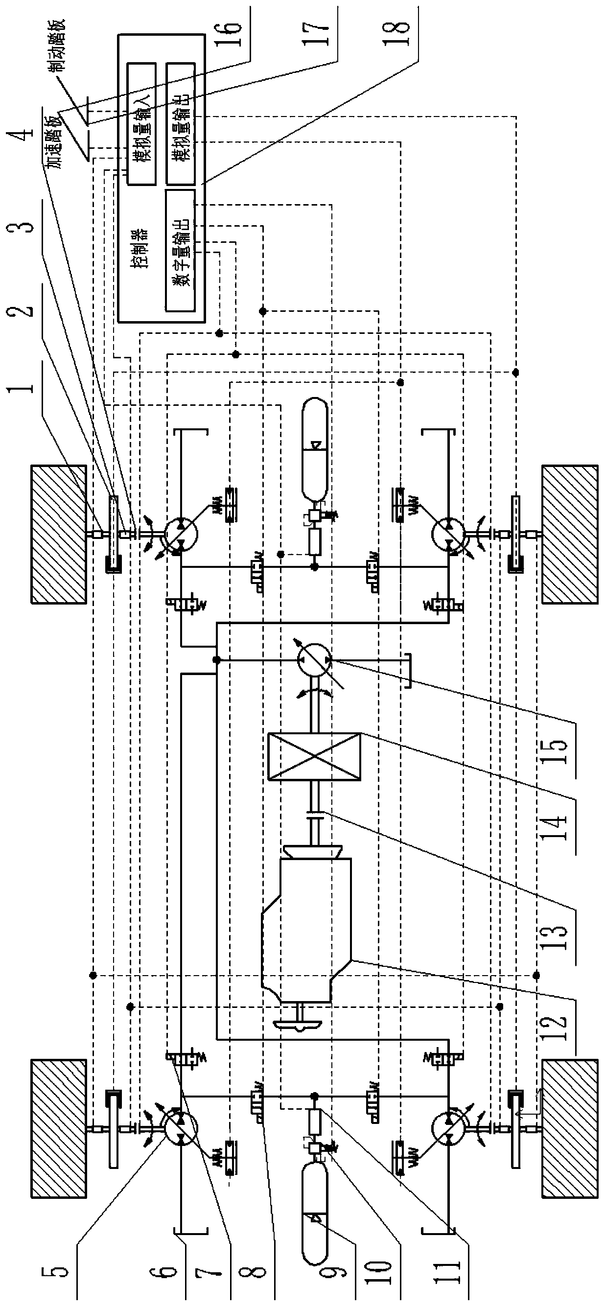
[0017] The hydraulic drive and regenerative braking energy recovery system includes: a speed sensor 1, a friction brake 2, a torque sensor 3, an electromagnetic clutch 4, a secondary element pump / motor 5, a hydraulic cylinder 6, a first two-position two-way electromagnetic Reversing valve 7, second two-position two-way electromagnetic reversing valve 8, high pressure accumulator 9, pilot pressure control valve 10, pressure sensor 11, engine 12, clutch 13, reduction box 14, hydraulic master cylinder 15, accelerator pedal 16, brake pedal 17, controller 18.

[0018] When the car is driving normally, the hydraulic braking energy recovery system does not participate in the work, at this time the second two-position two-way electromagnetic reversing valve 8 is in the normally open state, and the first two-position two-way electr...


PUM


Abstract

A regenerative braking energy recovery system of a hydraulically-driven automobile is characterized in that each wheel half axle of the automobile is provided with a secondary element pump / motor, andthe wheel half axles are connected with the secondary element pumps / motors through electromagnetic clutches; a torque sensor and a rotating speed sensor are installed on each wheel half axle; each secondary element pump / motor is connected with a hydraulic oil cylinder; each secondary element pump / motor is connected with a high-pressure energy accumulator through a second two-position two-way electromagnetic reversing valve; a pilot pressure control valve and a pressure sensor are connected with the oil outlet of each high-pressure energy accumulator, and each high-pressure energy accumulator is controlled to be connected and disconnected through the pilot pressure control valve; the secondary element pump / motor is connected with a hydraulic master pump through a first two-position two-wayelectromagnetic reversing valve; the hydraulic master pump is connected with the hydraulic oil cylinders through hydraulic pipelines; and the hydraulic master cylinder is sequentially connected with areduction gearbox, a clutch and an engine. All components are connected with a controller. The hydraulic regenerative braking recovery system is applied to an internal combustion engine passenger vehicle, so the complexity of the transmission structure of a traditional internal combustion locomotive is reduced.

Description

technical field [0001] The invention relates to a regenerative braking energy recovery system for a hydraulically driven vehicle. Background technique [0002] Under urban cycling conditions, the energy consumed by vehicle braking accounts for 31%-67% of the driving energy of the vehicle. Braking energy recovery technology can effectively improve the efficiency of energy use. In the energy braking recovery system, according to the different energy storage components, it is divided into electric regenerative braking, hydraulic regenerative braking, and flywheel regenerative braking: Although the electric regenerative braking system has a large energy density, it has a small power density and is unstable. Charging current will continue to consume battery life; flywheel regenerative braking energy efficiency is high, but flywheel cannot store energy for a long time, and when the car is turning at high speed, the torque generated by the rotation of flywheel will affect the steer...

Claims


Application Information

Patent Timeline
Patent Type & Authority Applications(China)
IPC IPC(8): B60K17/348B60T1/10B60T13/68
CPCB60K17/348B60T1/10B60T13/68
Inventor 宁晓斌包楠鑫李宁上官佳荣周航林亥博
Owner ZHEJIANG UNIV OF TECH
Why Eureka
Try Eureka