
Dust-free type textile equipment

A technology for textile equipment and piston blocks, which is applied in textiles and papermaking, etc., can solve the problems of lack of kinetic energy, poor dust removal effect, and lack of guide components, so as to ensure efficiency and increase practicability.

Inactive Publication Date: 2020-04-10
桐乡市麦西微服饰有限公司
View PDF1 Cites 0 Cited by
  • Summary
  • Abstract
  • Description
  • Claims
  • Application Information

AI Technical Summary

Problems solved by technology

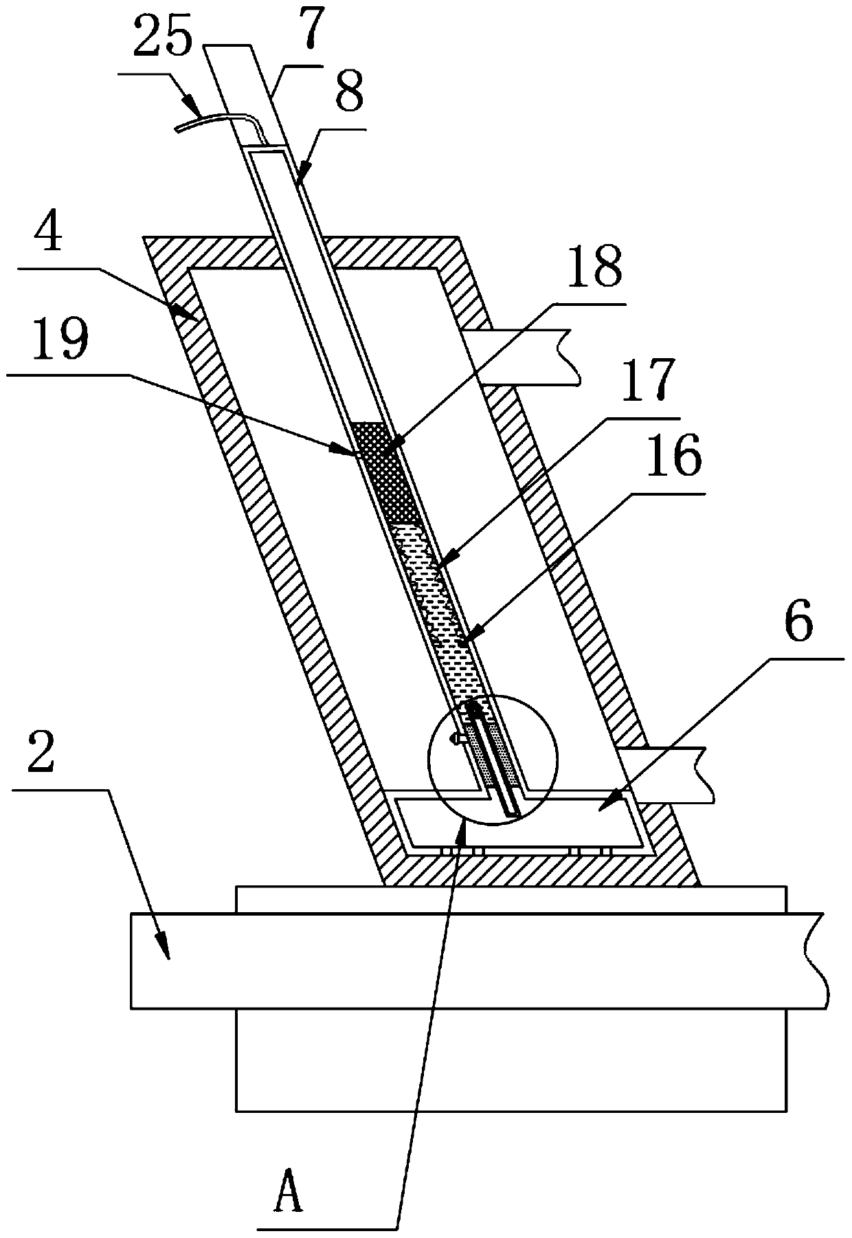
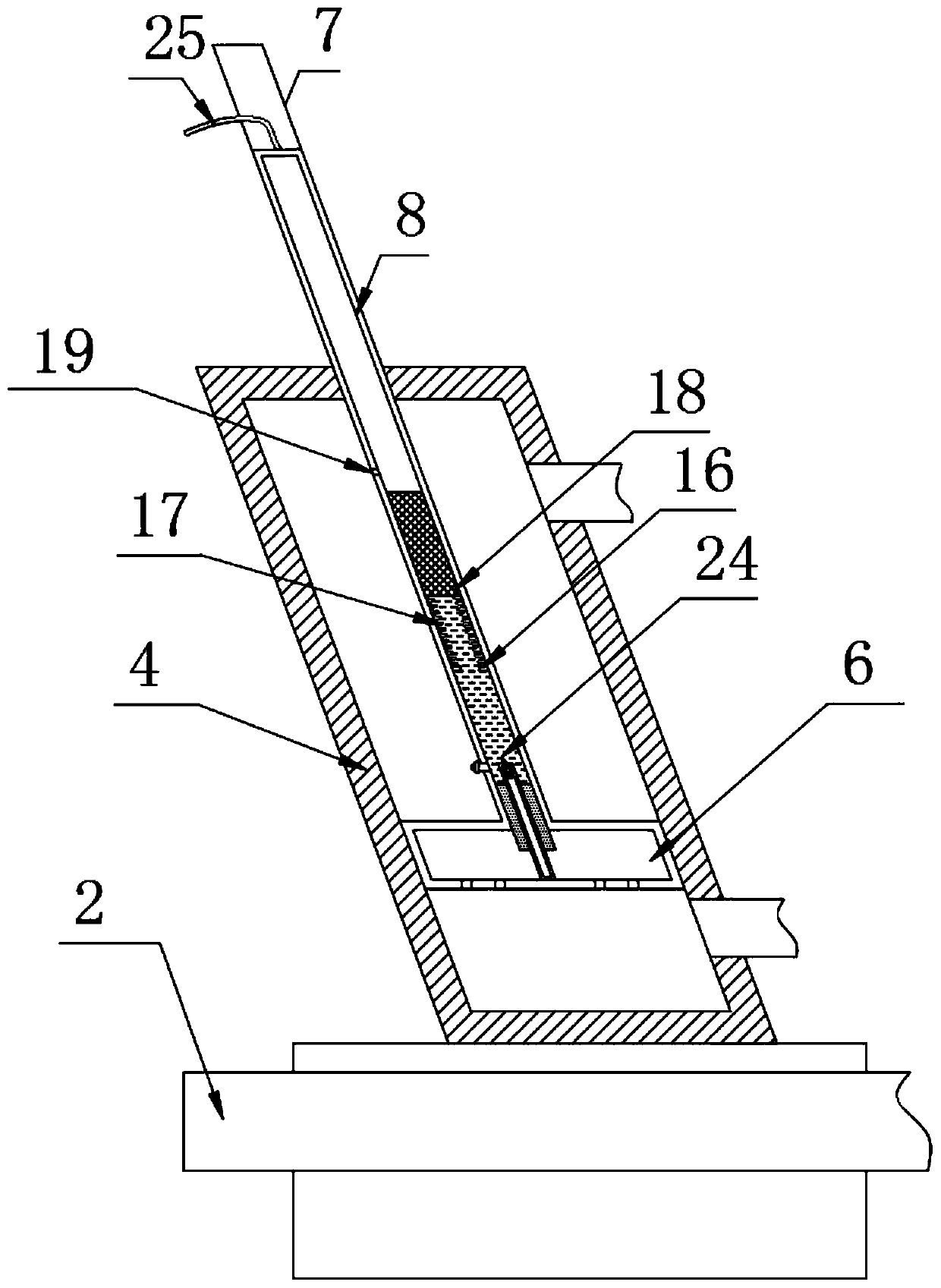
[0005] When the piston rod 7 moves up to drive the storage chamber 6 up, a negative pressure environment is formed between the bottom of the storage chamber 6 and the inner cavity of the piston cylinder 4, that is, the air pressure causes the flying dust and lint in the spinning frame 1 to enter This negative pressure environment, yet because there is the second air inlet 10, makes the bottom of the storage chamber 6 and between the inner chamber of the piston cylinder 4 and the storage chamber 6 be a whole negative pressure environment, so the whole negative pressure environment does not have A guide assembly, so that flying dust and flying lint cannot be directed into the insertion rod 14, even if the slide block 12 is moved down and the one-way valve 13 is opened due to the subsequent water injection into the water storage tank 8 through the water delivery pipe 9, however, the one-way valve 13 Without kinetic energy, the airflow in the negative pressure environment cannot be pumped into the water storage tank 8, and the entire water storage tank 8 is filled with water through the water delivery pipe 9. The interior of the entire water storage tank 8 is also a negative pressure environment, so it always has a certain dust removal effect, and it is difficult to quickly remove the negative pressure environment. Flying dust and flying lint in the water are quickly introduced into the inside of the water storage tank 8, so the dust removal effect of the whole device is extremely poor, and the operability is low

Method used


Image

  • Dust-free type textile equipment
  • Dust-free type textile equipment
  • Dust-free type textile equipment

Examples


Embodiment 2

[0037] Embodiment 2 specifically refers to the specification attached Figure 6-7

[0038] Embodiment 2 is specifically different from Embodiment 1 in that a first magnetic block 21 is fixedly installed on the bottom surface of the bar-shaped piston block 18, a second magnetic block 22 is fixedly installed on the inner wall of the water storage tank 8, and the first magnetic block 21 and the second magnetic block 22 are annular, and the top magnetic pole of the second magnetic block 22 is the same as the bottom magnetic pole of the first magnetic block 21 .

[0039] Using the above-mentioned technical means: utilizing the principle that the first magnetic block 21 and the second magnetic block 22 repel each other with the same pole, so that when the top of the bar-shaped piston block 18 loses the air pressure, the bar-shaped piston block 18 can be quickly moved upwards to recover, , so that the strip-shaped piston block 18 moves up and down in a reciprocating line, that is, wh...


PUM


Abstract

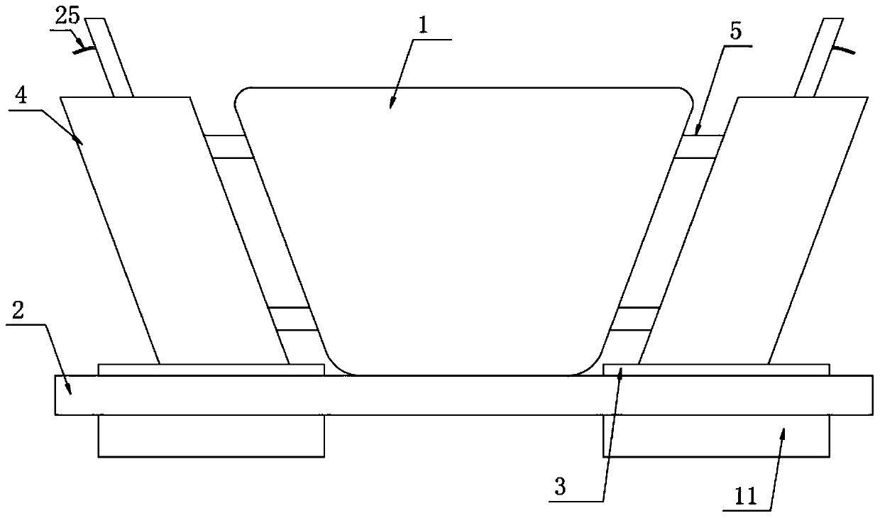
The invention discloses dust-free type textile equipment, and particularly relates to the field of textiles. The dust-free type textile equipment comprises a spinning frame, an engine base is fixedlyarranged at the bottom of the spinning frame, a left side and a right side of the spinning frame are communicated with piston cylinders through connecting pipes, a first support located at the top ofthe engine base is fixedly arranged at the bottom of each piston cylinder, second supports are fixedly arranged at a left end and a right end of a bottom surface of the engine base, a piston rod is movably arranged at the top of each piston cylinder in a sleeving manner, the bottom of each piston rod extends into the piston cylinder to integrally form a storage chamber, the internal of the storagechamber is a cavity, and a water storage tank is integrally formed in each piston rod. Since the gas injected into a gas guide pipe is uninterrupted in the operation stage, a bar-shaped piston blockcan move up and down in a reciprocating manner, that is, when the piston rod upwardly moves to the top, the sliding block still moves up and down to form a negative pressure environment for the bottomof the storage chamber, the dust collection efficiency of the device is greatly guaranteed, and the practicability of the device is increased.

Description

technical field [0001] The invention relates to the technical field of textiles, in particular to a dust-free textile equipment. Background technique [0002] In the production process of the textile machine, the yarn is easy to bring out flying dust and velvet, which has a serious impact on the products produced. For this phenomenon, it is necessary to install a vacuum cleaner in the production workshop and use the vacuum cleaner to clean the yarn. However, the vacuum cleaner is very noisy and generates heat, which eventually causes the staff in the production workshop to work at high temperatures all year round, which is likely to cause respiratory diseases. [0003] The invention patent of the patent application publication number CN108166114B, the reference manual is attached Figure 6-7 , specifically discloses a dust-free textile machine, comprising a machine base 2, a spinning frame 1 is installed above the machine base, and a dust suction device is installed on both ...

Claims


Application Information

Patent Timeline
Patent Type & Authority Applications(China)
IPC IPC(8): D01H11/00
CPCD01H11/005
Inventor 姚东鑫
Owner 桐乡市麦西微服饰有限公司
Learn More