Compressor, control method and air conditioner

A control method and compressor technology, applied in the field of compressors, can solve problems such as high viscosity of internal lubricating oil, high power consumption of compressors, difficulty in starting, etc., and achieve the effects of reduced power consumption, increased energy efficiency, and increased temperature

Active Publication Date: 2020-04-10
ZHUHAI GREE REFRIGERATION TECH CENT OF ENERGY SAVING & ENVIRONMENTAL PROTECTION
View PDF4 Cites 6 Cited by
  • Summary
  • Abstract
  • Description
  • Claims
  • Application Information

AI Technical Summary

Problems solved by technology

[0005] The purpose of the present invention is to overcome the deficiencies in the prior art and provide a compressor, a control method and an air conditioner, which are used to solve the problems of suction liquid in the current compressor at low temperature, difficulty in starting, internal lubricating oil viscosity, etc. Large, leading to the problem of high power consumption of the compressor

Method used


Image

  • Compressor, control method and air conditioner
  • Compressor, control method and air conditioner

Examples


Embodiment 1

[0029] Embodiment 1, a method for controlling a compressor.

[0030] This embodiment provides a compressor control method, including the following steps:

[0031] S1: Set the current of the motor 7 of the compressor 1 to X times the initial current;

[0032] The adjustment of the current magnitude when the motor 7 is in normal operation varies according to the load condition of the system. When the load of the compressor 1 is heavy and the torque requirement is large, the current passing through the motor 7 of the compressor 1 increases accordingly. Conversely, when the load of the compressor 1 is small and the torque requirement is small, the current passing through the motor 7 of the compressor 1 also decreases accordingly. After the compressor 1 is energized, the control module sets the current of the motor 7 of the compressor 1 to 1.4 times of the initial current, and realizes internal heating of the compressor 1 through the coil of the motor 7 of the compressor 1 and th...

Embodiment 2

[0039] Embodiment 2, a compressor.

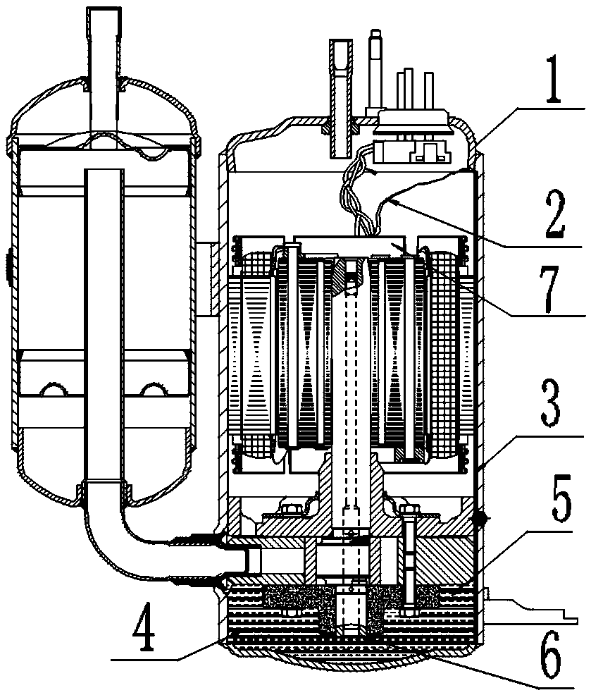
[0040] This embodiment provides a compressor such as figure 1 As shown, the compressor 1 of this embodiment is used to realize the control method of the compressor 1 described in the first embodiment.

[0041] Compressor 1 includes current transmission line 2, heating resistance wire, lubricating oil 5, motor 7, lubricating oil 5 temperature detection device, exhaust temperature detection device and control module, one end of current transmission line 2 is connected to the coil of motor 7, the other end of current transmission line 2 One end is connected to one end of the heating resistance wire, the other end of the heating resistance wire is immersed in lubricating oil 5, the lubricating oil 5 temperature detection device is set in the lubricating oil 5, the lubricating oil 5 temperature detection device is connected to the first port of the control module, and the exhaust The temperature detecting device is arranged at the exhaust port...

Embodiment 3

[0046] Embodiment 3, an air conditioner.

[0047] This embodiment provides an air conditioner, which includes the compressor 1 described in Embodiment 2.


PUM


Abstract

The invention provides a compressor, a control method and an air conditioner. The control method of the compressor includes the following steps of S1, setting a current of a motor of the compressor tobe X times an initial current; S2, obtaining the exhaust temperature T and the lubricating oil temperature K of the compressor in real time; and S3, adjusting the current of the motor of the compressor according to the magnitude of the fed-back exhaust temperature T and the fed-back lubricating oil temperature K. According to the compressor, the control method and the air conditioner, the currentof the motor of the compressor is increased under low frequency to increase heat output of a motor coil under a low frequency operation state, at the same time, heating of a heating resistance wire is utilized to heat up the temperature of a refrigerant in a shell and the temperature of lubricating oil in the compressor, and the effect of increasing the exhaust temperature in a compressor cavityis achieved; and at the same time, the temperature of the lubricating oil is increased, thus the temperature of the lubricating oil is increased, the viscosity is reduced, thus the capacity and the reliability of the compressor are ensured, power consumption of the compressor is decreased, and the energy efficiency is increased.

Description

technical field [0001] The invention relates to the technical field of compressors, in particular to a compressor, a control method and an air conditioner. Background technique [0002] At present, there are many air conditioners in the industry that use capillary tubes as throttling components in small household air-conditioning systems. Capillary tubes are widely used by most air-conditioning manufacturers because of their low cost and no moving parts. However, the adjustment ability of the capillary tube is poor, and the liquid supply volume cannot be adjusted arbitrarily according to the change of working conditions. Therefore, in the air conditioning system using the capillary tube as the throttling element, the state of the refrigerant at the outlet of the evaporator is unstable under the low-frequency working condition, and the degree of superheat is low. As a result, the suction state of the compressor is unstable, and there is liquid in the suction, so that there is...

Claims


Application Information

Patent Timeline
Patent Type & Authority Applications(China)
IPC IPC(8): F04C28/00F04C23/02F04C29/02F04C29/04F25B49/02F25B31/00
CPCF04C23/02F04C28/00F04C29/02F04C29/04F04C2270/195F04C2270/86F25B31/002F25B49/022F25B2500/16F25B2500/28
Inventor 魏腾飞贺申淦陈辉黄海伟谭章银李嘉雄黄振其
Owner ZHUHAI GREE REFRIGERATION TECH CENT OF ENERGY SAVING & ENVIRONMENTAL PROTECTION
Why Eureka
Try Eureka