Unmanned aerial vehicle path planning method based on control parameterization

A technology for controlling parameters and path planning, applied in the direction of non-electric variable control, control/regulation system, two-dimensional position/course control, etc., can solve problems such as nonlinearity, underactuation, and failure to consider UAV dynamic constraints. Achieve the effect of stable motor speed change, small optimal path error, and stable and feasible motion trajectory

Active Publication Date: 2020-04-10
SICHUAN UNIV
View PDF7 Cites 10 Cited by
  • Summary
  • Abstract
  • Description
  • Claims
  • Application Information

AI Technical Summary

Problems solved by technology

The dynamic model of the quadrotor UAV has the characteristics of nonlinearity, underactuation, and strong coupling, and the above algorithms do not consider the dynamic constraints of the UAV itself, so the calculated path is not optimal.
F

Method used


Image

  • Unmanned aerial vehicle path planning method based on control parameterization
  • Unmanned aerial vehicle path planning method based on control parameterization
  • Unmanned aerial vehicle path planning method based on control parameterization

Examples


Embodiment

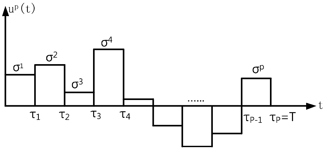
[0030] Such as Figure 1 to Figure 10 As shown, the UAV path planning method based on control parameterization mainly includes four steps: nonlinear programming modeling, control parameterization, constraint transcription processing and gradient formula solution.

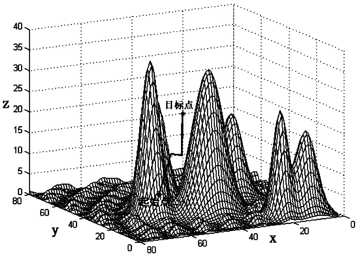
[0031] (S1) Nonlinear programming modeling: Select the state variables and control variables according to the nonlinear dynamic equation of the UAV and rewrite them into the form of a state space model, using the UAV's own performance index constraints and obstacles in the environment Object constraints, modeled as UAV continuous state inequality constraints, take the UAV's initial state and target point as the boundary constraint conditions, take the UAV flight time as the optimized objective function, and transform the UAV path planning problem into The nonlinear optimal control problem for the minimization of flight time of the UAV is to solve the optimal control variable u(t) to minimize the flight time T and sa...


PUM


Abstract

The invention discloses an unmanned aerial vehicle path planning method based on control parameterization. The unmanned aerial vehicle path planning method mainly comprises four steps of nonlinear programming modeling, control parameterization, constraint transcription processing and gradient formula solving. According to the invention, obstacle constraints in a 3D environment and dynamic constraints and performance index constraints of the unmanned aerial vehicle are comprehensively considered; two obstacle modeling methods are adopted, so that unmanned aerial vehicle path planning can meet the application of urban and mountainous environments; an optimal solution is solved and thus a state constraint condition and a control constraint condition are satisfied and an optimal time collision-free path of the unmanned aerial vehicle is obtained. The optimal path of the unmanned aerial vehicle obtained through the method is smoother than the optimal path obtained through the existing conventional RRT method and an A * method; the change of the rotating speed of a motor is more stable in the moving process of the unmanned aerial vehicle, and the moving track is stable and feasible.

Description

technical field [0001] The invention relates to the technical field of quadrotor unmanned aerial vehicle control, in particular, relates to a UAV path planning method based on control parameterization. Background technique [0002] Quadrotor UAV has the characteristics of vertical lift, fast flight speed, lightness and flexibility, so it has been widely used in many fields. For example, with the continuous development of drone aerial photography technology, when natural disasters occur, we need to understand the disaster situation in time, which requires drones to enter the disaster area and analyze the disaster situation through images. In addition, UAVs are also used in the field of traffic monitoring, which can monitor urban road conditions in real time, realize regional control, and ensure smooth traffic. For sudden traffic accidents, information can be transmitted in time to facilitate emergency rescue. The complexity of drone missions continues to increase. In order ...

Claims


Application Information

Patent Timeline
IPC IPC(8): G05D1/02G01C21/20
CPCG01C21/20G05D1/0221G05D1/0223
Inventor 李彬郭金龙吴昊李响刘鹭航毛新涛汤浩王振华张爱新马巍
Owner SICHUAN UNIV
Why Eureka
Try Eureka