Rotary transformer signal compensation method and device and rotary transformer

A resolver and signal compensation technology, which is applied in the direction of motor parameter estimation/correction, etc., can solve problems such as harmonic components in the resolver angle, complex signal demodulation and angle decoding, and motor output torque oscillation, etc., to achieve improved Effects of output torque stability, performance improvement, and balance improvement

Inactive Publication Date: 2020-04-10
SUNGROW POWER SUPPLY CO LTD
View PDF5 Cites 5 Cited by
  • Summary
  • Abstract
  • Description
  • Claims
  • Application Information

AI Technical Summary

Problems solved by technology

[0003] The signal demodulation and angle decoding of the resolver are relatively complicated, and the decoding of the resolver angle is usually realized by using a dedicated integrated IC chip or software
If the design or installation of the resolver is not ideal, or the consistency of the resolver sine-cosine signal processing circuit is not ideal, it will lead to harmonic components in the decoded resolver angle
The traditional motor control system usually directly uses the resolver angle obtained by IC chip decoding or software decoding as the original rotor angle of the motor, so that the harmonic components in the resolver angle will be directly introduced into the motor control system. In severe cases, it may even cause the output torque of the motor to oscillate or cause an overcurrent fault

Method used


Image

  • Rotary transformer signal compensation method and device and rotary transformer
  • Rotary transformer signal compensation method and device and rotary transformer
  • Rotary transformer signal compensation method and device and rotary transformer

Examples


Embodiment Construction

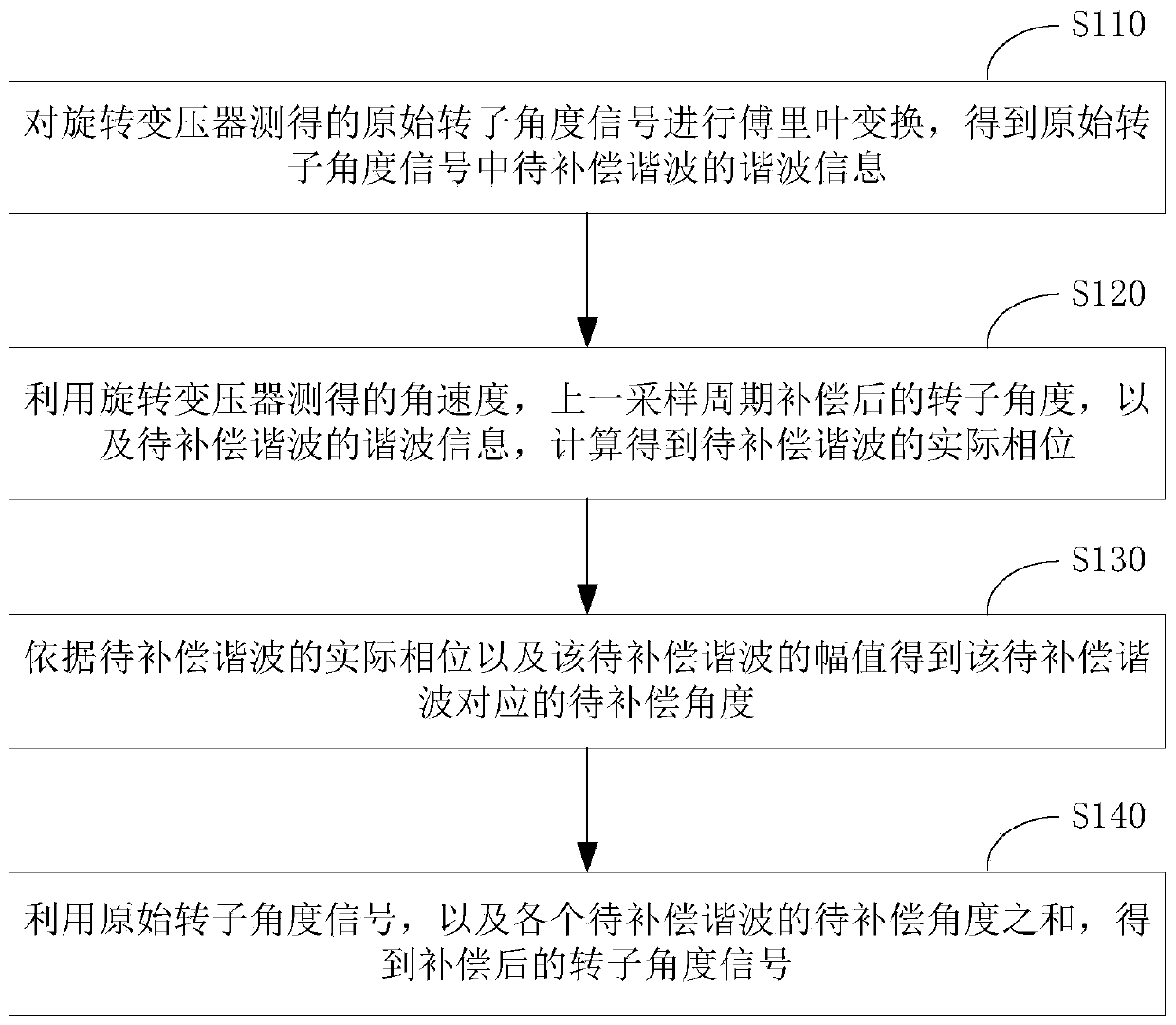
[0050] The working principle of the resolver is basically similar to the ordinary transformer, the difference is that the primary and secondary windings of the ordinary transformer are relatively fixed, so the ratio of the output voltage to the input voltage is constant, while the primary winding of the resolver follows the angular displacement of the rotor to produce a relative position Therefore, the magnitude of the output voltage changes with the change of the rotor angular displacement. The voltage amplitude of the output winding has a sine and cosine function relationship with the rotor angle, or maintains a certain proportional relationship, or has a certain relationship with the rotation angle within a certain range of rotation angle. linear relationship.

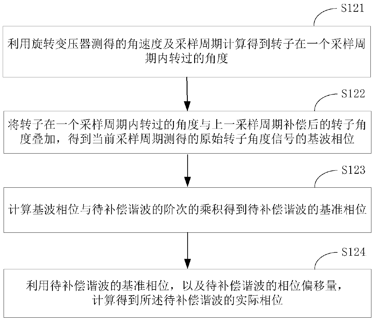
[0051] If the rotor angle decoded by the resolver contains harmonic components, the harmonic components will be directly introduced into the motor control system, thereby affecting the performance of the motor control ...


PUM


Abstract

The invention provides a rotary transformer signal compensation method and device and a rotary transformer. The method comprises steps of obtaining harmonic information of harmonic waves to be compensated in a measured original rotor angle signal; obtaining the actual phase of the to-be-compensated harmonic according to the currently measured angular velocity, the rotor angle compensated in the previous sampling period and the harmonic information of the to-be-compensated harmonic; obtaining a to-be-compensated angle corresponding to the to-be-compensated harmonic according to the actual phaseand amplitude of the to-be-compensated harmonic; finally, performing angle compensation on the original rotor angle signal according to the to-be-compensated angle of each to-be-compensated harmonicwave to obtain compensated rotor angle information, and inputting the compensated rotor angle information into next-stage control as the rotor angle of the motor. According to the scheme, the harmoniccomponent contained in the measured rotor angle signal is compensated to obtain the compensated rotor angle, so that the harmonic component in the rotor angle signal is suppressed, the influence of the harmonic component on the motor control system is avoided, and the performance of the motor control system is improved.

Description

technical field [0001] The invention belongs to the technical field of motor drive and control, and in particular relates to a resolver signal compensation method and device. Background technique [0002] A resolver (referred to as a resolver) is an electromagnetic sensor used to measure the angular displacement and angular velocity of a rotating object. It consists of a stator winding and a rotor winding. Among them, the stator winding is used as the primary side of the rotary transformer, and the rotor winding is used as the secondary side of the rotary transformer, and the induced voltage is obtained through electromagnetic coupling. [0003] The signal demodulation and angle decoding of the resolver are relatively complicated, and the decoding of the resolver angle is usually realized by using a dedicated integrated IC chip or software. If the design or installation of the resolver is not ideal, or the consistency of the resolver sine-cosine signal processing circuit is...

Claims


Application Information

Patent Timeline
Patent Type & Authority Applications(China)
IPC IPC(8): H02P23/14
CPCH02P23/14
Inventor 张乘玮陈文杰
Owner SUNGROW POWER SUPPLY CO LTD
Why Eureka
Try Eureka