Electronic equipment subrack and assembling method thereof

A technology for electronic equipment and assembly methods, applied in assembly machines, metal processing equipment, printed circuit board sockets, etc., can solve the problems of difficulty in ensuring the assembly accuracy of guide rails, a large number of parts, and a large number of included parts, and achieve light weight and assembly accuracy. High, low part count effect

Active Publication Date: 2020-04-10
INTEGRATED ELECTRONICS SYST LAB
View PDF17 Cites 1 Cited by
  • Summary
  • Abstract
  • Description
  • Claims
  • Application Information

AI Technical Summary

Problems solved by technology

The main problems are: 1. There are too many parts in the electronic equipment box; 2. The parts need to be manufactured with molds or profiles; 3. The key dimension chain (including the relative position and distance between the guide rails, the board panel mounting surface and The distance between the circuit board, the relative position of the guide rail groove and the connector on the circuit board) contains many parts, and it is difficult to ensure the assembly accuracy of the guide rail; 4. The assembly of the product is difficult

Method used


Image

  • Electronic equipment subrack and assembling method thereof
  • Electronic equipment subrack and assembling method thereof
  • Electronic equipment subrack and assembling method thereof

Examples


Embodiment Construction

[0023] Embodiments of the present invention will be described in detail below in conjunction with the accompanying drawings.

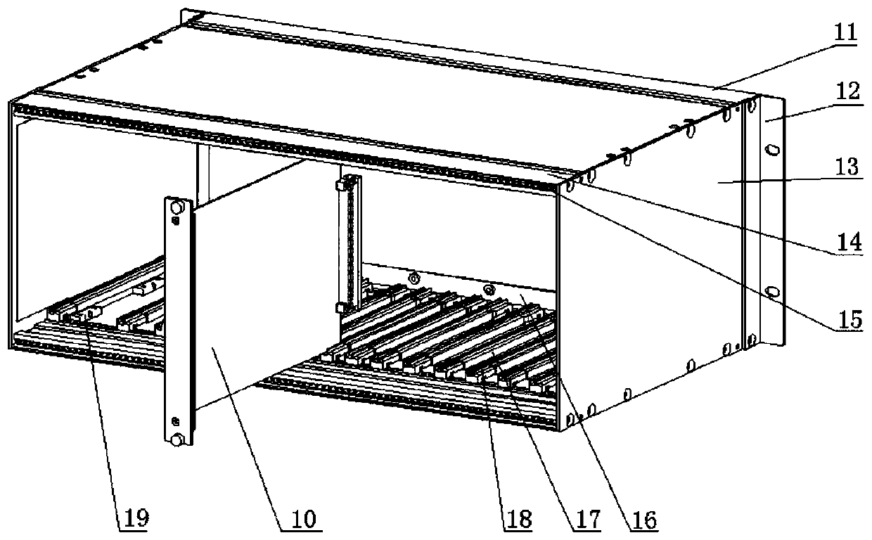
[0024] Such as figure 1 Shown is a schematic diagram of the overall structure of the existing electronic equipment sub-box. Most of the existing electronic equipment sub-boxes that meet the requirements of this standard are figure 1 The structural form shown in includes: front beam 11, side ear 12, side plate 13, rear beam 14, nut bar 15, motherboard mounting beam 16, profile guide rail 17, guide rail head 18, cover plate fixing block 19 and other main Parts, insert the universal board 10 into the profile guide rail 17 to complete the assembly of the equipment. The existing problems are: the number of parts is large; the parts need to be manufactured with molds or profiles; the critical dimension chain contains many parts, and it is difficult to ensure the assembly accuracy of profile guide rails; the assembly is difficult.

[0025] Such as figure...


PUM


Abstract

The invention relates to an electronic equipment subrack. The electronic equipment subrack is characterized in that when an upper guide rail plate and a lower guide rail plate are horizontally placed,the projection top view is rectangular, the subrack comprises a middle section of convex flat plate and a section of bent vertical plate positioned at the edge, and more than two guide rail grooves vertical to the vertical plate are formed in the convex flat plate; riveting nuts used for installing a circuit mother board are arranged on the bent vertical plate, and via holes used for installing parts are formed on the plane adjacent to the vertical plate and the plane away from the vertical plate; the side plates, a cross beam and the fixing lugs are provided with the connecting holes matchedwith the via holes of the upper guide rail plate and the lower guide rail plate respectively, nut holes are formed in the length direction of the cross beam and the two ends of the cross beam, and nut holes are formed in the two adjacent planes perpendicular to each other of a cover plate fixing block. The invention further relates to an assembling method of the electronic equipment subrack. Theelectronic equipment subrack has the obvious advantages of being small in number of parts, few in variety and low in manufacturing difficulty and being easy to assemble.

Description

technical field [0001] The invention belongs to the technical field of production and manufacturing of electric power system electronic equipment, and in particular relates to an electronic equipment insertion box with lower cost and more convenient assembly. Background technique [0002] GB / T19520 "Electronic Equipment Mechanical Structure 482.6mm (19in) Series Mechanical Structure Dimensions" stipulates the basic dimensions of 482.6mm (19in) series panels, subracks, chassis, racks and cabinets. At present, the existing electronic equipment sub-boxes in the market that meet the requirements of this standard usually include front beams, side ears, side panels, rear beams, nut strips, motherboard mounting beams, profile guide rails, guide rail heads, cover plate fixing blocks, etc. Numerous major parts. The main problems are: 1. There are too many parts in the electronic equipment box; 2. The parts need to be manufactured with molds or profiles; 3. The key dimension chain (i...

Claims


Application Information

Patent Timeline
Patent Type & Authority Applications(China)
IPC IPC(8): H05K7/14H05K7/18B23P21/00
CPCB23P21/00H05K7/1424H05K7/18
Inventor 丛振刚尹燕磊李波
Owner INTEGRATED ELECTRONICS SYST LAB
Why Eureka
Try Eureka