Volute edge-rolling forming special machine
A volute and hemming technology, which is applied in the field of volute hemming forming machine, can solve the problems of mechanization, high level of automation, complicated welding equipment, environmental impact, etc., and achieve the goal of eliminating welding pollution, stable product quality and improving production efficiency Effect
Active Publication Date: 2020-04-14
湖南创研智能机器人有限公司
6 Cites 0 Cited by
AI-Extracted Technical Summary
Problems solved by technology
The volute of the air duct of the existing range hood is generally produced by welding, and the side plate of the volute is welded to the surrounding plate. The welding equipment used in this process is re...
Method used
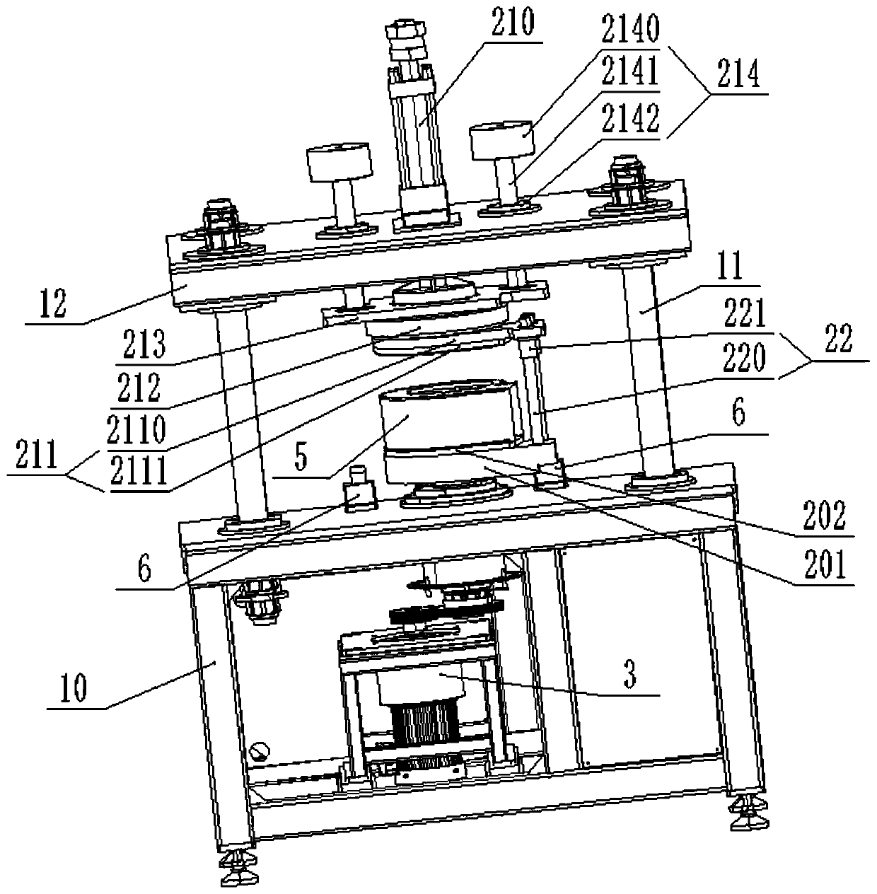
Further in this embodiment, as shown in Figure 3, the positioning mechanism 211 includes an upper die 2111 for the positioning of the side plate 51, and the first linear drive mechanism 210 is connected to the slewing support mounting seat 213. The slewing support 212 is connected, and the slewing support 212 is connected with the upper mold 2111 . Wherein the upper mold 2111 matches the shape of the side plate 51 to realize the precise positioning of the side plate 51 and improve the quality of rolling hemming. The inner ring of the slewing bearing 212 is fixed on the slewing bearing mounting seat 213, so that the inner ring of the slewing bearing 212 is fixed, and the upper mold 2111 is connected with the outer ring of the slewing bearing 212 through the upper mold mounting plate 2110, so that the upper mold 2111 and the upper mold are installed The plate 213 follows the outer ring of the slewing bearing 212 and can rotate relative to its inner ring.
In the present embodiment, the frame 1 is provided with the second buffer 4111 relative to the mobile base 4103, the third linear drive mechanism 4110 drives the mobile base 4103 to move, and the mobile base 4103 moves through the second buffer 4111. The cushioning and damping function of the time can effectively prot...
Abstract
The invention discloses a volute edge-rolling forming special machine which comprises a rack, a positioning and clamping device, a rotary driving device and a rolling and edge-covering device. The positioning and clamping device is mounted on the rack and is used for positioning and clamping a volute; the volute comprises a surrounding plate and two side plates located on the two sides of the surrounding plate respectively. The rotary driving device is mounted on the rack, is connected with the positioning and clamping device and drives the positioning and clamping device to rotate relative tothe rack. The rolling and edge-covering device is movably mounted on the rack and used for rolling and edge covering of the side edges of the side plates relative to the surrounding plate. The voluteedge-rolling forming special machine is simple and convenient in process, low in energy consumption, high in efficiency and free of environmental pollution.
Application Domain
Shaping toolsMetal-working feeding devices +2
Technology Topic
Structural engineeringEnergy consumption +5
Image
Examples
- Experimental program(1)
Example Embodiment
[0046] In order to enable those skilled in the art to better understand the technical solutions of the present invention, the present invention will be described in detail below with reference to the accompanying drawings. The description in this section is only exemplary and explanatory and should not have any limitation on the scope of protection of the present invention. .
[0047] It should be noted that similar reference numerals and letters indicate similar items in the following figures. Therefore, once an item is defined in one figure, it does not need to be further defined and explained in subsequent figures.
[0048] It should be noted that the terms "center", "upper", "lower", "left", "right", "vertical", "horizontal", "inner", "outer", etc. indicate the orientation or positional relationship: Based on the orientation or position relationship shown in the drawings, or the orientation or position relationship usually placed when the product of the invention is used, it is only for the convenience of describing the present invention and simplifying the description, and does not indicate or imply that the device or element referred to must It has a specific orientation, is constructed and operated in a specific orientation, and therefore cannot be understood as a limitation to the present invention. In addition, the terms "first", "second", "third", etc. are only used for distinguishing description, and cannot be understood as indicating or implying relative importance.
[0049] In addition, the terms "horizontal", "vertical", "overhanging" and other terms do not mean that the component is required to be absolutely horizontal or overhanging, but may be slightly inclined. For example, "horizontal" only means that its direction is more horizontal than "vertical", and it does not mean that the structure must be completely horizontal, but can be slightly inclined.
[0050] In the description of the present invention, it should also be noted that the terms "set", "installation", "connected", and "connected" should be interpreted broadly, unless otherwise clearly specified and limited. For example, it may be a fixed connection. Such as welding, etc.; it can also be detachable connection, such as bolt, screw connection, etc.; or integrally connected, such as integral molding, etc.; it can be mechanical connection or electrical connection; it can be directly connected or indirectly through an intermediate medium Connection can be the connection between two components. For those of ordinary skill in the art, the specific meanings of the above-mentioned terms in the present invention can be understood in specific situations.
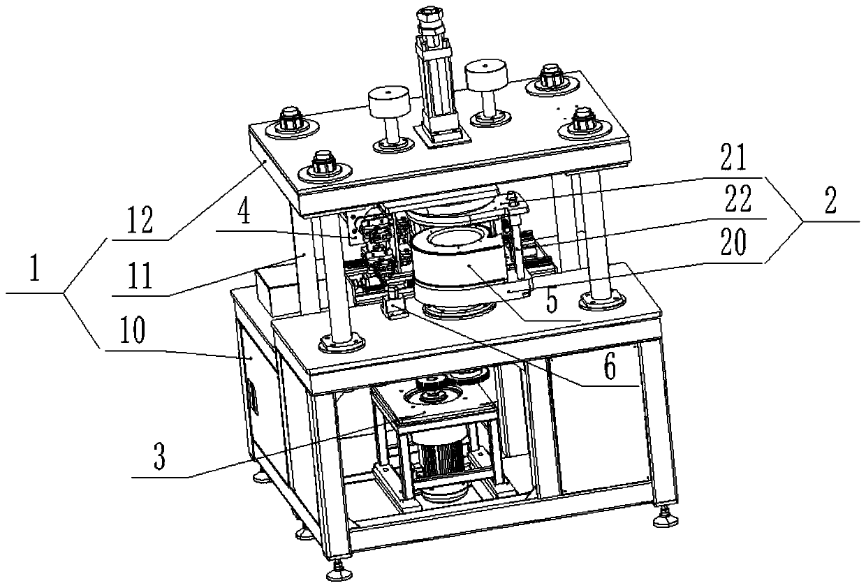
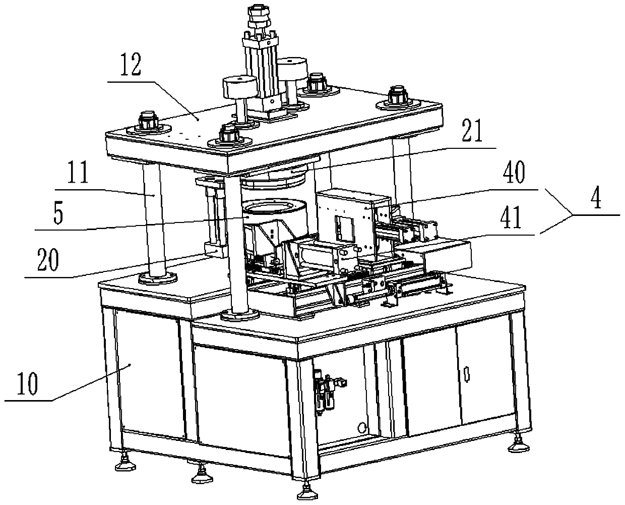
[0051] Such as Figure 1-18 As shown, the volute hemming forming machine provided by this embodiment includes:
[0052] Rack 1;
[0053] The positioning and clamping device 2 is installed on the frame 1 for positioning and clamping the volute 5; Figure 16 As shown, the volute 5 includes an enclosure 50 and two side plates 51 located on both sides of the enclosure 50;
[0054] Rotation drive device 3, said rotation drive device 3 is installed on said frame 1 and connected with said positioning and clamping device 2 to drive said positioning and clamping device 2 to rotate relative to said frame 1 ;
[0055] The rolling hemming device 4 is movably installed on the frame 1 and is used for rolling and hemming the side 510 of the side panel 51 relative to the enclosure panel 50, such as Figure 17 It is a schematic diagram of the structure when the side 510 of the side panel 51 is not rolled and hemmed with respect to the enclosure panel 50, Figure 18 It is a schematic diagram of the structure when the side 510 of the side panel 51 has been rolled and hemmed with respect to the enclosure panel 50.
[0056] In this embodiment, the positioning and clamping of the volute 5 is achieved by the positioning and clamping device 2 to ensure that the volute 5 will not be displaced when the rolling hemming device 4 is rolling and hemming, and the side of the side plate 51 is improved. The efficiency and quality of the 510 rolling hemming relative to the enclosure board 50. When the side 510 of the side plate 51 is rolled and hemmed with respect to the arc section of the enclosure plate 50, the rolling and hemming device 4 moves to the rolling position, and the rotation driving device 3 drives the positioning and clamping device 2 and the volute 5 to face each other By rotating the frame 1, the volute 5 rotates relative to the frame 1 to complete the rolling edge of the side 510 of the side plate 51 relative to the arc section of the enclosure plate 50. When the side 510 of the side plate 51 is rolled and hemmed relative to the non-circular arc section of the enclosure plate 50, the rotary drive device 3 does not act, and the rolling and hemming device 4 moves and rolls relative to the frame 1 to complete the side plate The non-circular arc section of the side 51 is relative to the rolling hemming of the enclosure board 50.
[0057] In this embodiment, as Image 6 As shown, the rotary drive device 3 includes a motor base 30, a motor 31, a transmission mechanism 32 connected to the motor 31, and a drive shaft 34 connected to the transmission mechanism 32. The motor base 30 is mounted on the frame 1. The motor 31 and the transmission mechanism 32 are mounted on the motor base 30, and the drive shaft 34 is mounted on the frame 1 through the first bearing base 33. The drive shaft 34 and the positioning clamping device 2 phase connection. The transmission mechanism 32 may be an existing gear mechanism, belt pulley mechanism, and the like.
[0058] Further in this embodiment, the rolling hemming device 4 includes:
[0059] R-angle hemming device 41, said R-angle hemming device 41 is movably installed on said frame 1, and is used for hemming of side 510 at R corner of said side plate 51 with respect to enclosure 50;
[0060] The rolling device 40 is movably installed on the frame 1 and used for rolling and encapsulating the side 510 of the non-R corner portion of the side plate 51 with respect to the enclosure 50.
[0061] In this embodiment, when the rolling hemming device 4 is rolling hemming, the R-angle hemming device 41 is first aligned with the R corner of the side plate 51, and then the R-angle hemming device 41 is moved relative to the frame 1 to complete the side plate 51 The side edge 510 at the corner R (non-circular arc section) is folded relative to the partial edge of the enclosure 50 to partially fix the side plate 51 and the enclosure 50, preventing the side plate 51 from being opposed to the side plate 51 when the subsequent rolling device 40 rolls the edge The hoarding 50 is scattered to improve the efficiency and quality of the rolling hemming. After the work of the R-angle hemming device 51 is completed, move it relative to the frame 1 and give way to the rolling device 40. At this time, the rolling device 40 moves relative to the frame 1 to align with the R corner where the hemming has been performed, and then cooperate Rotate the drive device 3 to complete the rolling hemming of the side 510 of the non-R part of the side plate 51 with respect to the enclosing plate 50, wherein the rolling device 40 rolls the hemming along the R corner of the hemming, effectively preventing the side The side 510 of the plate 51 is damaged, and at the same time, the efficiency of rolling and hemming is improved.
[0062] Further in this embodiment, the positioning and clamping device 2 includes:
[0063] The lower positioning device 20 is installed on the frame 1 and used for positioning the lower side plate 51; the lower positioning device 20 is connected with the rotation driving device 3;
[0064] The upper positioning and pressing device 21 is installed on the frame 1 and located above the lower positioning device 20 for positioning the lower side plate 51 and pressing the volute 5 ;
[0065] The upper positioning and pressing device 21 includes a first linear drive mechanism 210 installed on the frame 1 and a positioning mechanism 211 rotatably connected with the first linear drive mechanism 210; the rotary drive device 3 drives When the lower positioning device 20 rotates, the volute 5 and the positioning mechanism 211 follow the rotation of the lower positioning device 20.
[0066] When the volute 5 is installed in this embodiment, one side plate 51 is installed on the lower positioning device 20, the accurate positioning of the side plate 50 is realized under the lower positioning device 20, and then the enclosure 50 is installed on the side plate 51, Place the other side plate 51 on the enclosure 50, and then complete the positioning of the other side plate 51 and the compression of the volute 5 through the upper positioning and pressing device 21. Specifically, the positioning mechanism 211 realizes the positioning of the other side plate 51, and the positioning mechanism 22 is moved up and down by the expansion and contraction of the first linear drive mechanism 210, so that the volute 5 can be compressed by pressing the other side plate 51.
[0067] In this embodiment, the first linear drive mechanism 210 may use existing linear motion drive equipment such as oil cylinders, air cylinders, and electric push rods.
[0068] This embodiment further includes Figure 4 with 5 As shown, the lower positioning device 20 includes a base 201 connected to the rotation driving device 3, and a lower mold 202 disposed above the base 201 and used for positioning the side plate 51. The shape of the lower mold 202 and the side plate 51 are matched to realize the precise positioning of the side plate 51 and improve the quality of the rolling hemming. In this embodiment, the drive shaft 34 included in the rotation drive device 3 and the base 201 are connected by a key.
[0069] This embodiment further includes image 3 As shown, the positioning mechanism 211 includes an upper mold 2111 for positioning the side plate 51, and the first linear drive mechanism 210 is connected to the slewing support 212 through a slewing support mounting seat 213, and the slewing support 212 is connected with the upper mold 2111. The upper mold 2111 matches the shape of the side plate 51 to achieve precise positioning of the side plate 51 and improve the quality of the rolling hemming. The inner ring of the slewing bearing 212 is fixed on the slewing bearing mounting seat 213, so that the inner ring of the slewing bearing 212 is fixed, and the upper mold 2111 is connected to the outer ring of the slewing bearing 212 through the upper mold mounting plate 2110, so that the upper mold 2111 and the upper mold are installed The outer ring of the plate 213 following the slewing bearing 212 can rotate relative to its inner ring.
[0070] This embodiment further includes Figure 3-5 As shown, the upper mold 2111 and the lower mold 202 are guided by a guiding mechanism 22. Wherein the guide mechanism 22 includes a guide post 220 arranged vertically on the base 201, a bushing 221 arranged on the upper mold mounting plate 2110 and opposite to the guide post 220, the bushing 221 and The guide posts 220 are matched. When the first linear drive mechanism 210 drives the upper mold 2111 to move up and down, the movement accuracy of the upper mold 2111 relative to the lower mold 202 is ensured under the action of the bushing 221 and the guide post 220.
[0071] In this embodiment, the upper mold 2111 and the lower mold 202 are detachable, so that different upper molds 2111 and lower molds 202 can be replaced to complete the rolling hemming of the volute case 5 of different models, so that one machine has multiple functions.
[0072] Further in this embodiment, the frame 1 includes a base 10, a column 11 and an installation platform 12. The base 10 is connected to the installation platform 12 through a plurality of columns 11, wherein the number of the columns 11 is four. . The upper positioning and pressing device 21 further includes a limit mechanism 214, which includes a limit sleeve 2140 and a guide rod 2141; the first linear drive mechanism 210 is installed on the installation platform 12; The limit sleeve 2140 is located above the installation platform 12 and is connected to one end of the guide rod 2141; the other end of the guide rod 2141 passes through the through hole on the installation platform 12 and connects with the The linear drive mechanism 210 is connected. When the first linear drive mechanism 210 drives the positioning mechanism 211 to move up and down, the guide rod 2141 realizes the guidance of the positioning mechanism 211 to move up and down, and the mounting platform 12 is provided with a guide sleeve 2142 that cooperates with the guide rod 2141. At the same time, under the action of the limit sleeve 2140, the maximum limit of the downward movement of the positioning mechanism 211 is realized.
[0073] In this embodiment, the R-angle hemming device 41 includes an R-shaped extruded block 4101 for folding the side edge 510 at the R-corner of the side plate 51, which is similar to the R-shaped extruded block 4101. The connected second linear drive mechanism 4102 is connected to the second linear drive mechanism 4102 and is arranged on the third linear drive mechanism 4110 on the frame 1. The second linear drive mechanism 4102 is movably mounted on the On rack 1.
[0074] The working principle of the R-angle hemming device 41 in this embodiment is as follows:
[0075] The second linear drive mechanism 4102 drives the R-shaped extrusion block 4101 to move toward the R corner of the side plate 51, thereby completing the folding of the side edge 510 at the R corner of the side plate 51 relative to the enclosure 51, where the R-shaped extrusion block Under the action of 4101, the hemming of the sides 510 of the upper and lower side panels 51 of the enclosure board 50 is completed at one time, which is highly efficient; when the R-shaped extrusion block 4101 completes the hemming, the second linear drive mechanism 4102 drives the R-shaped extrusion The block 4101 returns to the initial position, and then under the action of the third linear drive mechanism 4110, the second linear drive mechanism 4102 and the R-shaped extrusion block 4101 are moved away as a whole to make way for the rolling device 40 behind.
[0076] In this embodiment, the R-angle hemming device 41 further includes a mobile base 4103, a first support 4104 and a second support 4105 alternately arranged on the mobile base 4103, wherein the second support 4105 passes through the first support 4105. The guide groove mechanism 4109 is movably mounted on the mobile base 4103, the fixed end of the second linear drive mechanism 4102 is fixed on the first support 4104, and the telescopic end of the second linear drive mechanism 4102 is connected to the second support 4105 R-shaped extrusion block 4101 is connected with the second support 4105, the movable base 4103 is provided with a limit block 4107 at one end close to the R-shaped extrusion block 4103, and the second support 4105 is provided with The first buffer 4106 and the stop bolt 4108 opposite to the first support 4104, the movable base 4103 is connected with the third linear drive mechanism 4110, and the movable base 4103 is mounted in a movable cooperation with the frame 1. When the second linear drive mechanism 4102 is extended, the second support 4105 moves on the moving base 4103, the R-shaped extrusion block 4101 moves toward the corner of the side plate 51, and when the limit bolt 4108 moves to touch the limit block At 4107, the second linear drive mechanism 4102 stops extending, and the R-shaped squeeze block 4101 completes the folding of the side edge 510 at the corner R of the side plate 51 relative to the enclosure plate 50; when the second linear drive mechanism 4102 contracts, the R-shaped squeeze block When the pressure block 4101 and the second support 4105 are retracted until the first buffer 4106 touches the first support 4104, the second linear drive mechanism 4102 stops contracting, and the first buffer 4106 serves as a buffer limiting function, effectively protecting the second Linear drive mechanism 4102 and R-angle hemming device 41.
[0077] In this embodiment, the frame 1 is provided with a second buffer 4111 opposite to the mobile base 4103, the third linear drive mechanism 4110 drives the mobile base 4103 to move, and the second buffer 4111 moves the base 4103 to buffer when the mobile base 4103 moves and limits. The shock absorption function effectively protects the third linear drive mechanism 4110 and the R-angle hemming device 41.
[0078] In this embodiment, the second linear drive mechanism 4102 and the third linear drive mechanism 4111 may use existing linear motion drive equipment such as oil cylinders, air cylinders, and electric push rods.
[0079] Further in this embodiment, the rolling device 40 includes a moving base 401 movably installed on the frame 1, a fourth linear drive mechanism 402 and a fifth linear drive mechanism 403 provided on the moving base 401, The sixth linear drive mechanism 406 connected to the movable seat 401 and arranged on the frame 1, the first roller assembly 404 connected to the fourth linear drive mechanism 402, and the fifth linear drive The second roller assembly 405 is connected to the mechanism 403. The first roller assembly 404 is used to perform the first positive rolling and hemming on the side 510 of the non-R corner portion of the side plate 51. The second roller The assembly 405 is used to perform a second reverse rolling and hemming on the side 510 of the non-R corner portion of the side plate 51.
[0080] The working principle of the rolling device 4 in this embodiment is as follows:
[0081] When the R-angle folding device 41 completes the folding of the side plate 51 at the R corner of the side 510 relative to the enclosure 50 and gives way, the sixth linear drive mechanism 406 drives the movable seat 401 to move from the initial position to the first position relative to the frame 1. The roller assembly 404 is aligned with the corner R where the hemming has been performed, the sixth linear drive mechanism 406 stops driving, and the fourth linear drive mechanism 402 drives the first roller assembly 404 to move toward the volute 5, so that the first roller assembly 404 enters After the rolling position, the fourth linear drive mechanism 402 stops moving. At this time, the rotary drive device 3 drives the lower positioning device 20, the volute 5 and the positioning mechanism 211 to rotate forward, so that the first roller assembly 404 completes the side plate 51 and the side 510 facing each other. After the first positive rolling and hemming of the arc section of the enclosure plate 50, the straight section of the side plate 51 is parallel to the moving direction of the movable seat 401 relative to the frame 1, at this time, the rotation driving device 3 stops moving, and the sixth straight line The driving mechanism 406 drives the moving seat 401 to move toward the initial position, so that the first rolling assembly 404 completes the first positive rolling and hemming of the side 510 of the side plate 51 relative to the linear section of the enclosure 50, and the sixth linear driving mechanism 406 Stop driving; further, the fourth linear drive mechanism 402 drives the first roller assembly 404 to return to the initial position, while the fifth linear drive mechanism 403 drives the second roller assembly 405 to move toward the volute 5 to the rolling position, the fourth linear The driving mechanism 402 stops moving. At this time, the sixth linear driving mechanism 406 drives the movable seat 401 to move away from the initial position, so that the second rolling assembly 405 completes the second reverse rolling of the side 510 of the side plate 5 relative to the linear section of the enclosure 50 After crimping, the sixth linear drive mechanism 406 stops driving, and the rotation drive device 3 drives the lower positioning device 2, the volute 5 and the positioning mechanism 211 to rotate in reverse, so that the second roller assembly 405 completes the side plate 51 and the side 510 facing each other. In the second reverse rolling of the arc section of the enclosure plate 50, the rotation driving device 3 stops moving, and the rolling device 40 and the R-angle hemming device 41 return to their original positions, thus completing the side plate 51 The side 510 at the corner R is rolled twice relative to the enclosure 50 to prevent the side 510 of the side plate 51 from rebounding after the first positive rolling is completed. Under the action of the two rolling, the side 510 of the side plate 51 Compared with the hoarding 50, the rolling hemming effect is good and the quality is stable.
[0082] In this embodiment, the first roller assembly 404 and the second roller assembly 405 are aligned with the two side plates 51 and are provided with one each, so as to complete the rolling hemming of the sides 510 of the two side plates 51 with respect to the enclosure 50 at one time.
[0083] In this embodiment, the fourth linear drive mechanism 402, the fifth linear drive mechanism 403, and the sixth linear drive mechanism 406 may use existing linear motion drive equipment such as oil cylinders, air cylinders, and electric push rods.
[0084] Further in this embodiment, the first roller assembly 404 includes a first roller mounting frame 4040 connected to the fourth linear drive mechanism 402, a roller 4041 that is rotatably mounted on the first roller bracket 4040, and The second roller 4042, the first roller 4041 performs a 30°-60° pre-rolling bending on the side 510 of the side plate 51, specifically, the roller one 4041 is provided with a 30°-60° rolling cone along the circumference On the other hand, the second roller 4042 pre-rolls the side 510 of the side plate 51 to 90° roll-wrapped edge.
[0085] The working principle of the first roller assembly 404 in this embodiment is as follows:
[0086] When the first roller assembly 404 completes the first positive rolling and hemming of the side 510 of the side panel 51 relative to the enclosure 50, firstly, a roller 4041 completes the 30° of the side 510 of the side panel 51 relative to the enclosure 50. -60° pre-rolling and bending, and then through the second roller 4042 to complete the side plate 51 side 510 relative to the coaming plate 50 after the pre-rolling and de-bending 90° rolling hemming, effectively reducing the side plate 51 side 510 For the degree of damage, if the 90° rolling hemming is performed directly, the angle at the intersection of the rolled portion of the side 510 of the side plate 51 and the unrolled portion is too large, which will cause the side 510 of the side plate 51 to be damaged or torn.
[0087] Further in this embodiment, the second roller assembly 405 includes a second roller mounting frame 4050 connected to the fifth linear drive mechanism 403, and a third roller 4051 rotatably mounted on the second roller support 4050, so The roller three 4051 performs 90° rolling and hemming on the side 510 of the side plate 51.
[0088] In this embodiment, the first roller mounting frame 4040 is connected with a first rail seat 407, and the movable seat 401 is provided with a first rail 410 that matches the guide groove on the first rail seat 407. The fixed end of the four linear drive mechanism 402 is mounted on the movable base 401 through the first bracket 408, and the telescopic end of the fourth linear drive mechanism 402 is connected to the first rail base 407, and the first rail base 407 and Under the action of the first guide rail 410, the first roller mounting frame 4040 moves and guides relative to the movable seat 401.
[0089] In this embodiment, the second roller mounting frame 4050 is connected with a second rail seat 414, and the movable seat 401 is provided with a second rail 411 that matches the guide groove on the second rail seat 414. The fixed end of the five linear drive mechanism 403 is mounted on the movable base 401 through the second bracket 415, and the telescopic end of the fifth linear drive mechanism 403 is connected to the second rail base 414, and the second rail base 414 and Under the action of the second guide rail 411, the movement and guiding function of the second roller mounting frame 4050 relative to the movable base 401 is realized.
[0090] In this embodiment, the frame 1 is provided with a bottom frame 412, and the bottom frame 412 is provided with a guide rail 413, wherein the movable base 4103 included in the R-angle hemming device 41 is provided with a guide groove matching the guide rail 413 Similarly, the movable seat 401 included in the rolling device 40 is provided with a guide groove that cooperates with the guide rail 413, that is, the R-angle hemming device 41 and the rolling device 40 are movably installed on the chassis 412. Preferably, the sixth linear drive mechanism 406 includes a hood 4060, a motor 4064, a reducer 4065, a ball screw 4061 and a nut 4066, the hood 4060 is mounted on the chassis 412, the motor 4064 and the reducer 4065 is located in the hood 4060, and the motor 4064 is connected to the reducer 4065; the two ends of the ball screw 4061 are rotatably mounted on the chassis 412 through the second bearing seat 4062, and one end is connected to the reducer 4065 is connected, the nut 4066 is sheathed on the ball screw 4061 to realize the spiral linear transmission. The nut 4066 is connected to the moving base 401 through the bottom plate 4063, and the guide groove on the moving base 401 is provided with the bottom of the bottom plate 4063. In this embodiment, the second buffer 4111 is mounted on the bottom frame 412 via a buffer mounting seat 4112.
[0091] In this embodiment, the volute hemming forming machine further includes a detection device 7, which is installed on the rotation driving device 3, and is used for controlling the rotation according to the rotation position of the lower positioning device 20. Start and stop of the drive device 3. Specifically, such as Image 6 with 7 As shown, the detection device 7 includes a proximity switch 70, a baffle 71, and a controller. Specifically, the controller adopts an existing Mitsubishi FX3U-64MT. The proximity switch 70 and the rotary drive device 3 are all connected to the controller. The proximity switch 70 is mounted on the first bearing seat 33 and is stationary relative to the frame 1; the baffle 71 is mounted on the drive shaft 33; when the rotary drive device 3 rotates, the baffle 71 rotates with the drive shaft 33, and when the baffle When 71 rotates to the position where it is aligned with the proximity switch 70, it sends a message to the controller, and the controller controls the rotating drive device 3 to stop rotating. The number of proximity switches 70 is determined according to the rotation start and stop positions of the lower positioning device 20. In this embodiment, under the action of the detection device 7, the start and stop of the rotation driving device 3 are precisely controlled.
[0092] Further in this embodiment, the volute hemming forming machine further includes a telescopic blocking device 6, the telescopic blocking device 6 is installed on the frame 1, and the lower positioning device 20 is provided with the telescopic The bottom hole 2010 is matched with the blocking device 6, and the telescopic blocking device 6 is used to fix the position of the lower positioning device 20. In this embodiment, when the lower positioning position 20 does not move and the roll-wrapping device 2 moves, for example, when the roll-wrapping device 40 completes the roll-wrapping of the side 510 of the side panel 51 with respect to the side panel 50, the expansion and contraction block The device 6 is extended and inserted into the bottom hole 2010 of the lower positioning device 20, thereby preventing the lower positioning device 20 from being loaded and moving during the rolling process of the rolling device 40, ensuring that the lower positioning device 20 is effectively fixed and improving the volute The efficiency and quality of rolling hemming.
[0093] In this embodiment, as Figure 15 As shown, the telescopic blocking device 6 includes a seventh linear drive mechanism 60 provided on the frame 1, connected to a fixed end of the seventh linear drive mechanism 60 and provided with a fixing seat 61 on the frame 1, a device The guide shaft 62, which is on the fixed seat 61 and connected to the telescopic end of the seventh linear drive mechanism 60, is telescopically driven by the seventh linear drive mechanism 60 to expand and contract the guide shaft 62 so as to be inserted into the bottom hole 2010 of the lower positioning device 20 Or come out from the bottom hole 2010 of the lower positioning device 20. Preferably, the shaft end of the guide shaft 62 has a tapered structure to perform a guiding function during insertion. In this embodiment, the base 201 included in the lower positioning device 20 is provided with a bottom hole 2010.
[0094] In this embodiment, the seventh linear drive mechanism 60 may use existing linear motion drive equipment such as oil cylinders, air cylinders, and electric push rods.
[0095] This embodiment eliminates the welding pollution caused by the existing welding and the large consumption of electric energy, and because there are fewer welding spots, the original cold plate material volute can be changed to stainless steel or galvanized plate. The process of surface treatment can be omitted, and the production efficiency is improved while reducing the production cost.
[0096] It should be noted that in this article, the terms "include", "include" or any other variants thereof are intended to cover non-exclusive inclusion, so that a process, method, article or device including a series of elements not only includes those elements, It also includes other elements not explicitly listed, or elements inherent to the process, method, article, or equipment.
[0097] The above shows and describes the basic principles, main features and advantages of the present invention. Those skilled in the industry should understand that the present invention is not limited by the above-mentioned embodiments. The above-mentioned embodiments and the description only illustrate the principles of the present invention. The present invention will have various aspects without departing from the spirit and scope of the present invention. Various changes and improvements, these changes and improvements fall within the scope of the claimed invention. The scope of protection claimed by the present invention is defined by the appended claims and their equivalents.
PUM


Description & Claims & Application Information
We can also present the details of the Description, Claims and Application information to help users get a comprehensive understanding of the technical details of the patent, such as background art, summary of invention, brief description of drawings, description of embodiments, and other original content. On the other hand, users can also determine the specific scope of protection of the technology through the list of claims; as well as understand the changes in the life cycle of the technology with the presentation of the patent timeline. Login to view more.
Similar technology patents
Method for harmlessly treating trash flying ash by adopting trash-burning process
Owner:CHONGQING ANGRUIYUE SCI & TECH
Treating method for oily sludge
Owner:安徽省通源环境节能股份有限公司
Periclase-ferroalumina spinal brick and its making process
Owner:WUHAN UNIV OF SCI & TECH
Preparation of antibacterial nano filter membrance
Owner:SHANGHAI UNIV
Preparation method of Apremilast
Owner:徐州鑫辉生物能源科技有限公司
Classification and recommendation of technical efficacy words
- Simple process
- Reduce energy consumption
Multimedia data recording apparatus, monitor system, and multimedia data recording method
Owner:PANASONIC INTELLECTUAL PROPERTY CORP OF AMERICA
Simultaneously desulfurization and denitration wet ammonia flue gas cleaning technology and system thereof
Owner:WUHAN KAIDI ELECTRIC POWER ENVIRONMENTAL
Method for recycling metal oxide from waste flue gas denitration catalyst
Owner:HUADIAN ELECTRIC POWER SCI INST CO LTD
Method for preparing graphite alkyne film
Owner:INST OF CHEM CHINESE ACAD OF SCI
Preparation method of high-strength hydrogel
Owner:HENAN POLYTECHNIC UNIV
Catalyst for gas phase hydrogenation of acetic acid to prepare ethanol
Owner:DALIAN INST OF CHEM PHYSICS CHINESE ACAD OF SCI +1
Light emitting diode based linear lamps
Owner:INTEMATIX
Wireless emergency lighting system
Owner:RING LLC