Laser cutting machine

A laser cutting machine and frame technology, which is applied in laser welding equipment, abrasive jet machine tools, used abrasive processing devices, etc., can solve the problems of difficult cleaning and easy sticking of waste materials, and achieve the effect of easy processing

Active Publication Date: 2020-04-14
浙江威克环境艺术工程有限公司
View PDF14 Cites 13 Cited by
  • Summary
  • Abstract
  • Description
  • Claims
  • Application Information

AI Technical Summary

Problems solved by technology

[0003] The surface of the workbench of the existing laser cutting machine is composed of multiple vertical support plates, and the top of the support plate is provided with teeth. During the working process of the laser cutting machine, the waste materials cut out by the laser gun group are easily pasted after being melted. On the support plate, the waste material is not easy to clean off from the support plate after cooling

Method used


Image

  • Laser cutting machine
  • Laser cutting machine
  • Laser cutting machine

Examples


Embodiment Construction

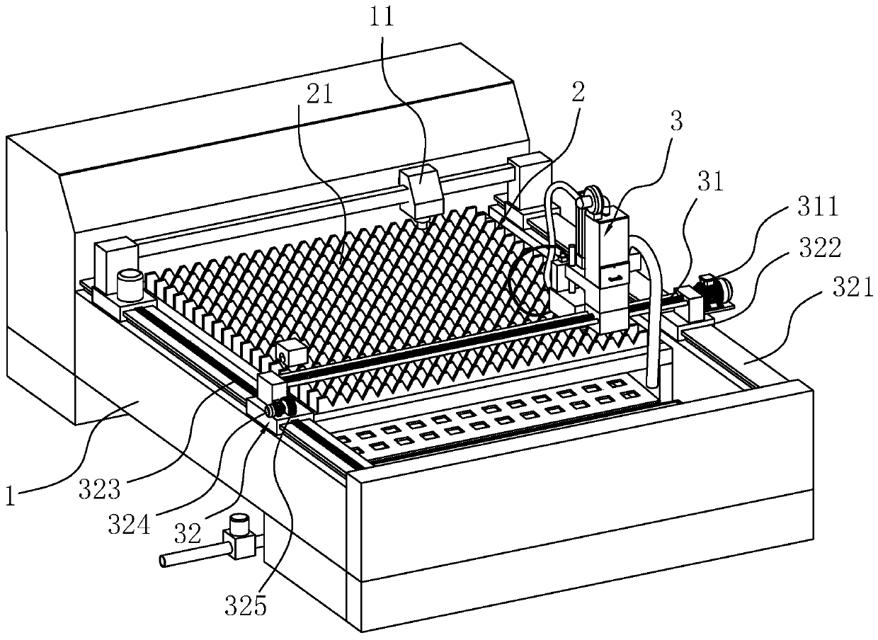
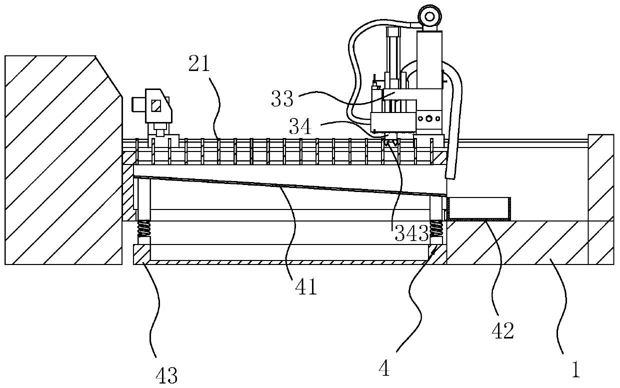
[0037] A laser cutting machine, see figure 1, including a frame 1, the top of the frame 1 is fixed with a horizontally placed support platform 2, and the support platform 2 is evenly fixed with a plurality of support plates 21 along the length direction of the frame 1, and a plurality of support plates 21 are formed between adjacent support plates 21. The gap, the top of the support plate 21 is tooth-like, the top of the frame 1 is horizontally slidably connected to the laser gun 11, and the top of the support platform 2 is provided with a cleaning mechanism 3 for cleaning the waste pasted on the support plate 21.

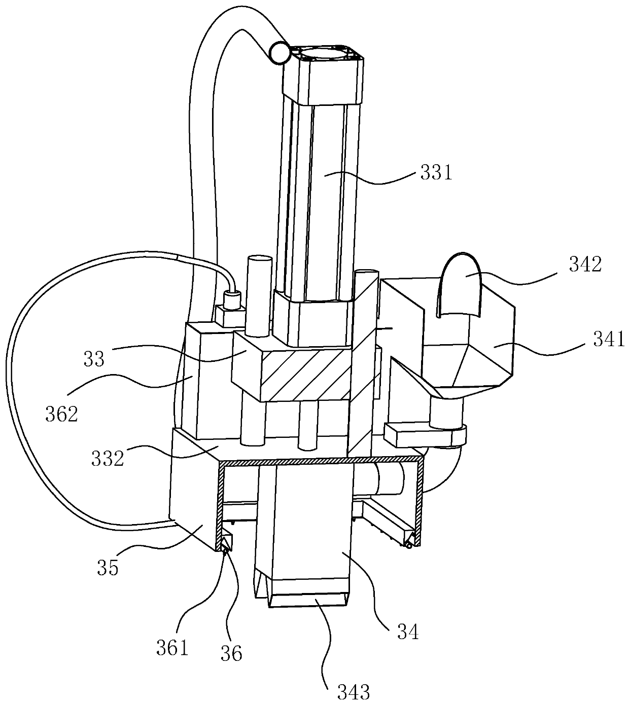
[0038] see figure 1 and figure 2 The cleaning mechanism 3 includes a screw rod 31 horizontally slidably connected to the top of the frame 1. The axial direction of the screw rod 31 is parallel to the extension direction of the support plate 21. Sliding drive assembly 32 . The driving assembly 32 includes a sliding plate 322 fixed on both ends of the screw rod 3...


PUM


Abstract

The invention discloses a laser cutting machine, and belongs to the field of laser cutting equipment. The laser cutting machine comprises a machine frame, a supporting platform is fixedly arranged atthe top of the machine frame, wherein the supporting platform comprises a plurality of supporting plates which are uniformly and fixedly arranged in the length direction of the machine frame, a clearing mechanism for clearing waste materials on the supporting plates is arranged at the top of the machine frame, the clearing mechanism comprises a screw rod horizontally slidably connected to the topof the machine frame, the axial direction of the screw rod is arranged parallel to the extending direction of the supporting plates, the end part of the screw rod is connected with a driving assemblyfor driving the screw rod to horizontally slide along the top of the machine frame, the top of the screw rod is horizontally slidably connected with a fixing seat in the axial direction of the screw rod, one end of the screw rod is fixedly connected with a driving motor for driving the screw rod to rotate, a hydraulic cylinder is fixedly arranged at the top of the fixing seat, a cylinder body of the hydraulic cylinder is fixedly connected to the top of the fixing seat, a piston rod of the hydraulic cylinder extends to the bottom of the fixing seat and is fixedly connected with a fixing plate,and a shot blasting device is fixedly arranged at the bottom of the fixing plate. The laser cutting machine has the effect that the clearing mechanism can automatically clear the waste materials on the supporting plates.

Description

technical field [0001] The invention relates to the field of laser cutting equipment, in particular to a laser cutting machine. Background technique [0002] Laser cutting is to use the energy released when the laser beam irradiates the surface of the workpiece to melt and evaporate the workpiece to achieve the purpose of cutting and engraving. In the field of metal cutting machinery, laser cutting machines have become the mainstream production machinery. In terms of cutting, they not only have high processing precision but also high production efficiency. Metal support member, laser gun group, auxiliary air supply system and control part. During the production process, the laser gun group moves vertically and laterally to complete the shape cutting of the metal on the metal support member. The laser gun group irradiates the laser beam The energy released on the surface of the workpiece melts the target position at a high temperature, and the molten metal liquid phase is bl...

Claims


Application Information

Patent Timeline
Patent Type & Authority Applications(China)
IPC IPC(8): B23K26/38B23K26/70B24C3/32B24C9/00
CPCB23K26/38B24C3/32B24C9/003B23K26/702
Inventor 宫威郑叶萍
Owner 浙江威克环境艺术工程有限公司
Why Eureka
Try Eureka