Movable unmanned aerial vehicle empennage

A technology of unmanned aerial vehicle and empennage, which is applied in aircraft parts, aircraft control, aircraft stability, etc. It can solve the problems of aircraft stability and maneuverability deterioration, heavy structural weight, complex mechanism, etc., and achieve light mechanism and simple empennage structure , Improve the effect of pitching stability and agility

Inactive Publication Date: 2020-04-14
XIAN AIRCRAFT DESIGN INST OF AVIATION IND OF CHINA
View PDF6 Cites 0 Cited by
  • Summary
  • Abstract
  • Description
  • Claims
  • Application Information

AI Technical Summary

Problems solved by technology

However, in the current variant aircraft with retractable wings, when the wings are expanded or retracted, the position of the center of gravity and the aerodynamic focus of the aircraft will change accordingly, and the stability and maneuverability of the aircraft will deteriorate.
In addition, the deformation drive mostly chooses hydraulic drive, screw screw drive and other forms, the mechanism is complex, and the structure is heavy.

Method used


Image

  • Movable unmanned aerial vehicle empennage

Examples


Embodiment Construction

[0016] The invention belongs to the technical field of UAV design and relates to a movable UAV tail. The empennage of the invention has a simple structure and a lightweight mechanism, and can move along the course according to changes in flight missions and environments, and change the tail volume of the aircraft through the change of the length of the tail arm, thereby improving the pitching stability and the stability of the aircraft within a certain range. agility. At the same time, the retractable tail arm is also convenient for storage in the machine bank.

[0017] Through specific examples, the technical solution of the present invention is further illustrated.

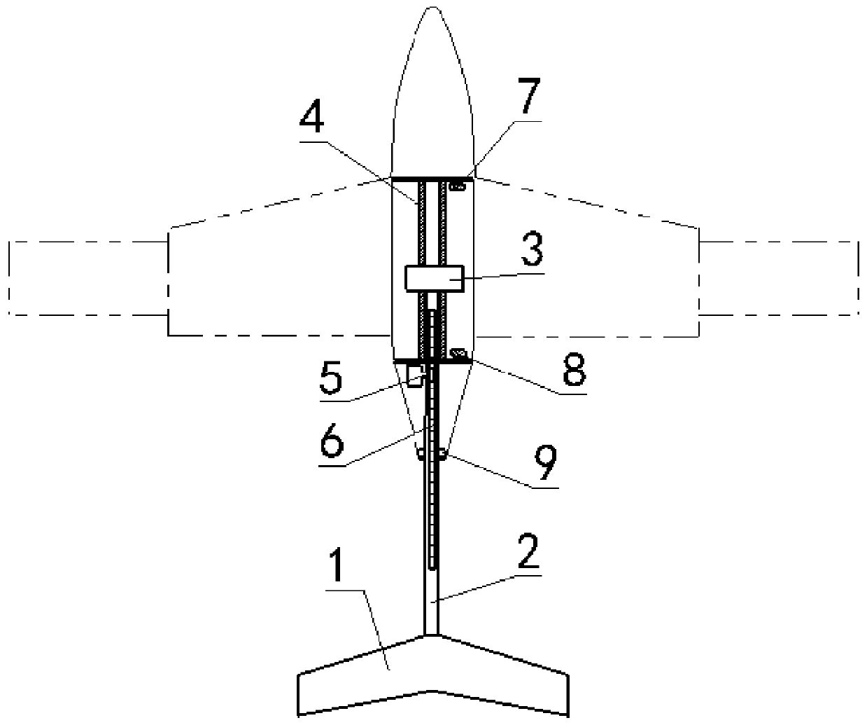
[0018] A kind of movable UAV empennage of the present invention, its structure is by empennage body 1, tail arm 2, slide block 3, slide rail 4, drive gear 5, rack 6, first position sensor 7, second position sensor 8 and roller 9 form.

[0019] The empennage body 1 is a full-height honeycomb sandwich structure...


PUM


Abstract

The invention provides a movable unmanned aerial vehicle empennage. The movable unmanned aerial vehicle empennage comprises an empennage body 1, a tail force arm 2, a sliding block 3, a sliding rail 4, a driving gear 5, a rack 6, a first position sensor 7, a second position sensor 8 and a rolling wheel 9. A sliding rail 4 is arranged in the middle of the fuselage in the axis direction of the aircraft, a sliding block 3 is fixedly arranged at the front end of the tail force arm 2, a rack 6 is installed on the upper surface of the tail force arm 2, and an empennage driving gear 5 is arranged atthe tail of the fuselage. The sliding block 3 slides on the sliding rail 4, and the rack 6 is connected with the driving gear 5 in a meshed mode. A first position sensor 7 is arranged on the front side of the sliding rail 4, and a second position sensor 8 is arranged on the rear side of the sliding rail 4; when the sliding block 3 drives and drives the tail force arm 2 and the empennage body 1 tomove to the preset forward maximum position, the tail force arm 2 and the empennage body 1 stop moving forwards by touching the first position sensor 7; and the two rollers 9 are respectively arrangedon two sides of the tail force arm 2 on the rear side of the body.

Description

technical field [0001] The invention belongs to the technical field of variant aircraft design, and relates to a movable UAV tail. Background technique [0002] Variant drones refer to unmanned aerial vehicles that change the overall configuration through materials, structures and mechanisms, advanced flow and flight control to adapt to different mission requirements and obtain the best performance in different flight states. . A common variant UAV is a variant aircraft with retractable wings. It has a great ability to change the aspect ratio of the aircraft, which has a significant impact on the endurance of the aircraft. Through the expansion and contraction of the wings, a wide range of changes in the wing area can be achieved. Meet the needs of different flight states and tasks. However, in the current variant aircraft with retractable wings, the position of the center of gravity and the aerodynamic focus of the aircraft will change after the wings are expanded or retr...

Claims


Application Information

Patent Timeline
Patent Type & Authority Applications(China)
IPC IPC(8): B64C5/02B64C5/12
CPCB64C5/02B64C5/12
Inventor 黎欣
Owner XIAN AIRCRAFT DESIGN INST OF AVIATION IND OF CHINA
Why Eureka
Try Eureka