Multi-mode ultra-thin light source device of phase contrast microscope and using method thereof

A technology of phase contrast microscope and light source device, applied in microscopes, optics, optical components, etc., to achieve the effects of accurate measurement, guaranteed illumination range and simple structure

Pending Publication Date: 2020-04-14
上海观纳智能科技有限公司
View PDF3 Cites 0 Cited by
  • Summary
  • Abstract
  • Description
  • Claims
  • Application Information

AI Technical Summary

Problems solved by technology

[0004] The purpose of the present invention is to provide a multi-mode ultra-thin light source device for a phase contrast microscope and its use method, so as to solve the shortcomings of the existing light source device proposed in the above-mentioned background technology

Method used


Image

  • Multi-mode ultra-thin light source device of phase contrast microscope and using method thereof
  • Multi-mode ultra-thin light source device of phase contrast microscope and using method thereof
  • Multi-mode ultra-thin light source device of phase contrast microscope and using method thereof

Examples


Embodiment example 1

[0030] Implementation Case 1: Phase Contrast Imaging

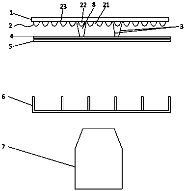
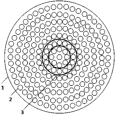
[0031] First, select the phase-contrast imaging mode, and then light up the middle annular array 22 of the LED array 2 in the circle where the transparent light guide ring 3 is located, the transparent light guide ring 2 can effectively prevent the light emitted by the middle annular array 22 of the LED array 2 from diffusing outwards , the light becomes more uniform after passing through the diffuser plate 4, and after passing through the glass 5, it is irradiated on the object in the porous plate 6, and is enlarged by the objective lens 7 to form a phase contrast image.

Embodiment example 2

[0032] Implementation Case 2: Brightfield Imaging

[0033] First, select the bright field imaging mode, and then light up the entire LED array 2. The light emitted by the LED array 2 becomes more uniform after passing through the diffuser plate 4. After passing through the glass 5, it is irradiated on the object in the porous plate 6, and then passes through the objective lens 7. Magnified to form bright field imaging.

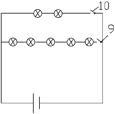
[0034] Circuit schematic diagram of the present invention, that is, the LED lights on the inner circular array 21 and the outer annular array 23 are arranged in parallel with the LED lights on the middle annular array 22, and the LED lights on the inner circular array 21 and the outer annular array 23 are electrically connected with The first switch 9 is electrically connected to the LED lights on the ring array 22 with the second switch 10 . In addition, all LED lights can be controlled separately to form different angles of lighting as required.


PUM


Abstract

The invention discloses a multi-mode ultra-thin light source device of a phase contrast microscope and a using method thereof. The multi-mode ultra-thin light source device comprises an LED array, anLED base, a transparent light guide ring, a light scattering plate and glass. The LED array is welded to the LED base for fixation. One end of the transparent light guide ring sleeves the inner side and the outer side of the middle annular array of the LED array, the other end of the transparent light guide ring is connected with the light scattering plate, the light scattering plate homogenizes light emitted by LED lamps; and the glass is tightly attached outside the light scattering plate and used for fixing the light scattering plate and the transparent light guide ring. According to the light source device, switching of two imaging modes of phase contrast illumination and bright field illumination can be realized through circuit switching, the total height is smaller than 20 mm, and the light source device can be quite conveniently applied to a microscope with the high automation degree requirement.

Description

technical field [0001] The invention relates to a component of a phase contrast microscope, in particular to a light source device of a phase contrast microscope and a method for using the same. Background technique [0002] Phase contrast microscope is the most commonly used microscope in biological research. Biological research often observes thin and transparent samples, such as cells. Because they are too thin and transparent, such samples are often difficult to observe under ordinary optical microscopes. directly seen. When we observe cells in middle school biological experiments, we often use a specific dye to stain the cells, or directly observe colored cells, such as onion epidermal cells. However, in actual biological research, we need a method that can directly observe cells without processing, and phase-contrast microscopy solves this problem well. After the illumination light passes through the transparent sample, the image cannot be directly observed due to th...

Claims


Application Information

Patent Timeline
Patent Type & Authority Applications(China)
IPC IPC(8): G02B21/14G02B21/12
CPCG02B21/12G02B21/14
Inventor 范永涛罗海清孙彦华李杰
Owner 上海观纳智能科技有限公司
Why Eureka
Try Eureka