Current conversion method and device of controllable reactor
A technology of converter devices and reactors, which is applied in the direction of output power conversion devices, harmonic reduction devices, and conversion equipment that can be converted to DC without intermediate conversion. It can solve the problem of voltage spikes damaging switching devices and increasing the current of switching devices. Stress, increased loss and other issues, to achieve the effect of small loss, simple control and high reliability
- Summary
- Abstract
- Description
- Claims
- Application Information
AI Technical Summary
Problems solved by technology
Method used
Image

Examples
Embodiment 1
[0031] The first embodiment of the present invention provides a method for commutating a controllable reactor, and the method includes the following steps:
[0032] Obtain the switching command of the inductor and the current magnitude of the current;
[0033] The switching device of the controllable reactor is controlled to be turned off or turned on in response to the switching instruction according to the zero-crossing point of the current current.
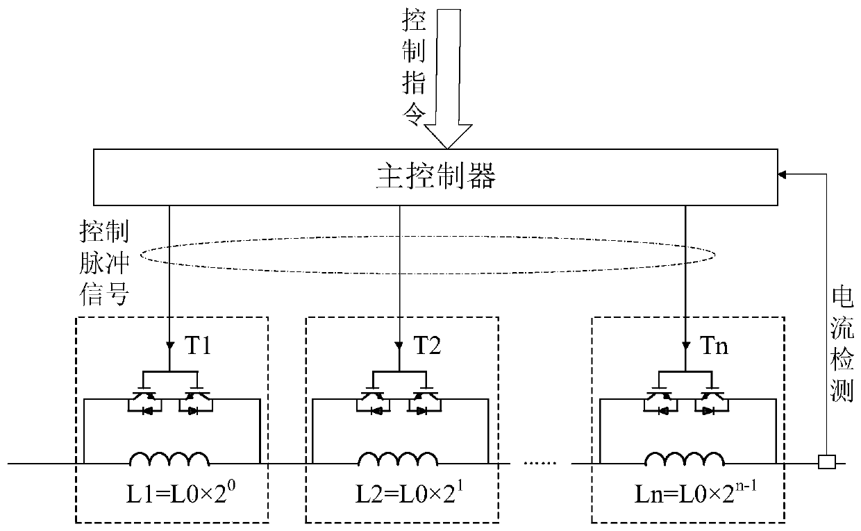
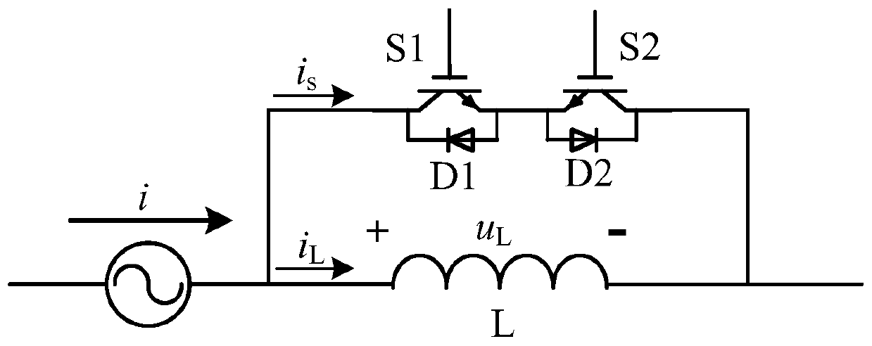
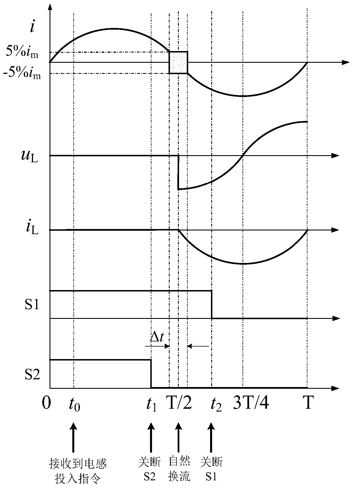
[0034] Specifically, in this embodiment, a group of controllable reactance modules connected in parallel with bidirectional switches and inductors is used as an example, and the commutation method of multiple controllable reactance modules can be deduced by analogy, such as figure 2 As shown, two full-control switching devices IGBT, IGCT or MOSFET are used in reverse series as a bidirectional switch, and each switching device S1 and S2 includes an anti-parallel diode D1 and D2 respectively. When the switches S1 and S2 are tur...
Embodiment 2
[0068] The second embodiment of the present invention provides a method for commutating a controllable reactor, and the method includes the following steps:
[0069] Obtain the switching command of the inductor and the current magnitude of the current;
[0070] The switching device of the controllable reactor is controlled to be turned off or turned on in response to the switching instruction according to the zero-crossing point of the current current.
[0071] Specifically, in this embodiment, a group of controllable reactance modules connected in parallel with bidirectional switches and inductors is used as an example, and the commutation method of multiple controllable reactance modules can be deduced by analogy, such as figure 2 As shown, two full-control switching devices IGBT, IGCT or MOSFET are used in reverse series as a bidirectional switch, and each switching device S1 and S2 includes an anti-parallel diode D1 and D2 respectively. When the switches S1 and S2 are tu...
Embodiment 3
[0090] The third embodiment of the present invention provides a converter device for a controllable reactor, the device includes:
[0091] The command receiving module is used to obtain the switching command of the inductor;
[0092] The current sampling module is used to obtain the current current magnitude;
[0093] The switch control module is used to control the switching device of the controllable reactor to turn off or turn on in response to the switching instruction according to the zero-crossing point of the current current.
PUM
 Abstract
Description
Claims
Application Information
 - R&D
- Intellectual Property
- Life Sciences
- Materials
- Tech Scout
- Unparalleled Data Quality
- Higher Quality Content
- 60% Fewer Hallucinations
Browse by: Latest US Patents, China's latest patents, Technical Efficacy Thesaurus, Application Domain, Technology Topic, Popular Technical Reports.
© 2025 PatSnap. All rights reserved.Legal|Privacy policy|Modern Slavery Act Transparency Statement|Sitemap|About US| Contact US: help@patsnap.com