
Vapor chamber-type heat dissipation device

A technology of heat dissipation device and vapor chamber, which is applied in cooling/ventilation/heating transformation, modification using liquid cooling, electrical components, etc. It can solve problems such as poor operation of electronic equipment, and achieve enhanced convective heat transfer and circulation speed. , the effect of increasing the area of ​​heat dissipation

Active Publication Date: 2020-04-14
GUANGDONG UNIV OF TECH
View PDF10 Cites 0 Cited by
  • Summary
  • Abstract
  • Description
  • Claims
  • Application Information

AI Technical Summary

Problems solved by technology

At present, most electronic and electrical equipment on the market mainly use axial flow fans, cooling fins, and heat pipes for air convection heat dissipation. 2 The electronic equipment heat dissipation system can play a very good heat dissipation effect, but when the heat flux density of electronic equipment is relatively large, for example, it is between 1 and 10W / cm 2 Within the range, the heat absorption and heat dissipation effect of the axial flow fan combined with the heat dissipation fins and heat pipes for air convection heat dissipation cannot meet the needs of electronic equipment with high heat flux density, resulting in the problem that electronic equipment is prone to poor operation

Method used


Image

  • Vapor chamber-type heat dissipation device
  • Vapor chamber-type heat dissipation device
  • Vapor chamber-type heat dissipation device

Examples


Embodiment

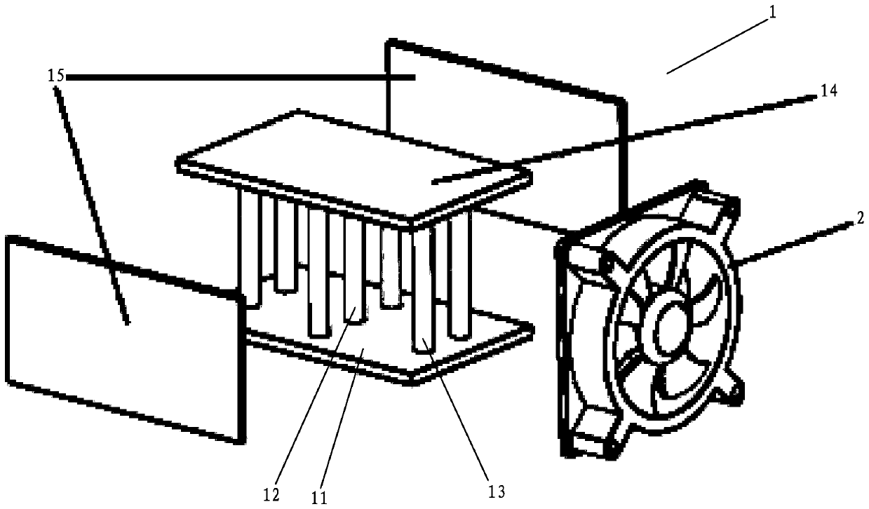
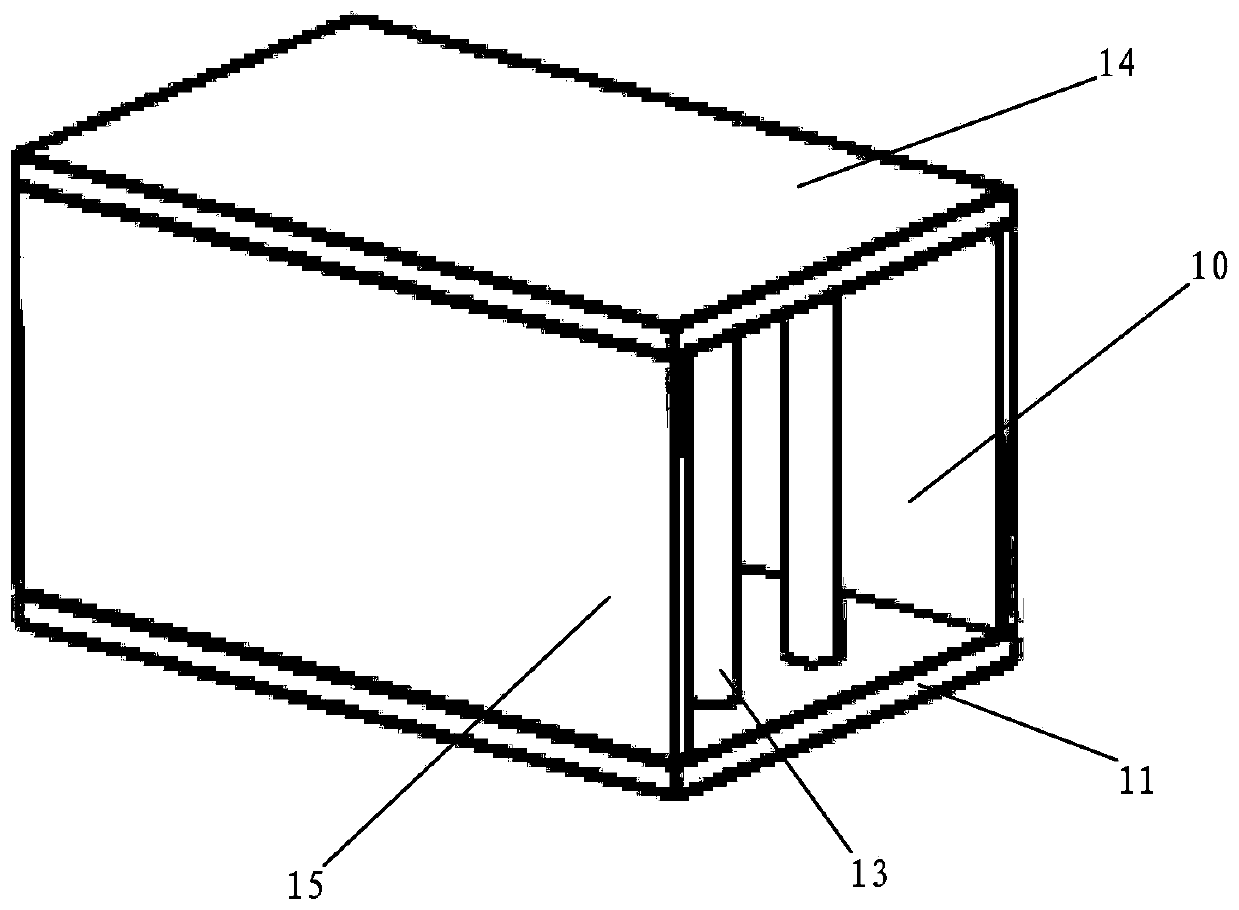
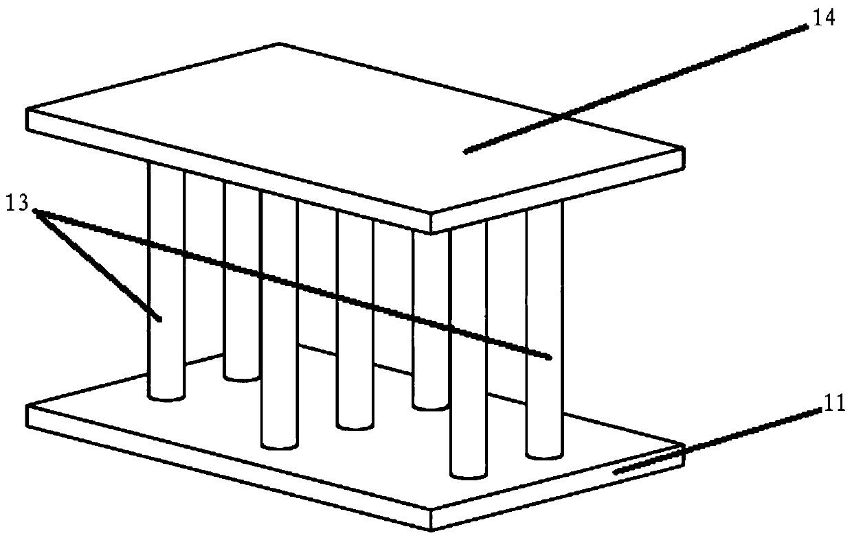
[0023] refer to Figure 1 to Figure 3 ,as well as Figure 5 , this embodiment relates to a vapor chamber heat dissipation device, including a heat conductor 1 and a fan 2, the heat conductor 1 is provided with an air duct 10, and the fan 2 is arranged on one end of the air duct 10; the heat conductor 1 includes an evaporation plate 11. Steam pipe 12, return pipe 13, condensing plate 14 and side plate 15. The evaporating plate 11 is in contact with the heat source to absorb the heat of the heat source. The evaporating plate 11 and the condensing plate 14 are hollow structures. The steam pipe 12 and the Both ends of the return pipe 13 are respectively connected and communicated with the evaporating plate 11 and the condensing plate 14 to form a sealed space; the side plates 15 are set to two and are respectively arranged on two opposite sides of the evaporating plate 11 and the condensing plate 14. On the side; the steam pipe 12 is arranged in the middle of the evaporating plat...


PUM


Abstract

The invention discloses a vapor chamber-type heat dissipation device, which comprises a heat conductor and a fan, and an air duct is arranged in the heat conductor; the heat conductor comprises an evaporation plate, a steam pipe, return pipes, a condensation plate and a side plate, the evaporation plate makes contact with the heat source to absorb heat of the heat source, the evaporation plate andthe condensation plate are each of a hollow structure, and the two ends of the steam pipe and the two ends of the return pipe are connected and communicated with the evaporation plate and the condensation plate correspondingly to form a sealed space; the steam pipe is arranged in the middle of the evaporation plate and the condensation plate; the return pipes are arranged at the head ends and thetail ends of the middles of the evaporation plate and the condensation plate; the sealed space is in a vacuum state and is filled with a liquid working medium, after the evaporation plate absorbs heat, the liquid working medium is vaporized and sequentially flows into the steam pipe, the condensation plate, the return pipes and the evaporation plate, and a heat absorption-heat dissipation circulation loop is formed; the whole sealed space is of a heat conduction structure, the heat dissipation area is greatly increased, the purposes of heat absorption and heat dissipation are rapidly achieved, and the heat conduction performance and efficiency are high.

Description

technical field [0001] The invention relates to a heat dissipation device, in particular to a vapor chamber type heat dissipation device. Background technique [0002] With the rise of new energy vehicles, the promotion of LEDs in the lighting market, the miniaturization of digital products such as computers, and the use of compact chips, the power density of electronic products is becoming higher and higher. The technical requirements have been greatly improved, and heat dissipation technology has become an important factor restricting product development. At present, most electronic and electrical equipment on the market mainly use axial flow fans, cooling fins, and heat pipes for air convection heat dissipation. 2 The electronic equipment heat dissipation system can play a very good heat dissipation effect, but when the heat flux density of electronic equipment is large, for example, it is between 1 ~ 10W / cm 2 Within the range, the heat absorption and heat dissipation e...

Claims


Application Information

Patent Timeline
IPC IPC(8): H05K7/20
CPCH05K7/2029H05K7/20327
Inventor 胡锦鹏王长宏扬淇钧王雪
Owner GUANGDONG UNIV OF TECH
Features
  • Generate Ideas
  • Intellectual Property
  • Life Sciences
  • Materials
  • Tech Scout
  • Unparalleled Data Quality
  • Higher Quality Content
  • 60% Fewer Hallucinations
Learn More