
Angle valve rod joint line removing device

A clamping line and valve stem technology, which is applied in the field of powder metallurgy, can solve the problems that the clamping line cannot be completely removed, affects the sealing performance of the product, and increases the difficulty of the clamping line, so as to eliminate the risk of water leakage and improve the rationality and simplicity , The effect of enhancing product competitiveness

Pending Publication Date: 2020-04-17
HEFEI HUIZHI NEW MATERIAL TECH CO LTD
View PDF0 Cites 0 Cited by
  • Summary
  • Abstract
  • Description
  • Claims
  • Application Information

AI Technical Summary

Problems solved by technology

At present, manual grinding is mostly used to remove the parting line. Although it is simple and convenient to use and does not require technical processing, it is bound to be accompanied by low efficiency.
In particular, the size of the angle valve stem itself is small, and there are multiple sets of annular installation grooves arranged on the turning surface, and the shape and contour are relatively complicated, which further increases the difficulty of manually removing the parting line for angle valve mechanisms.
When workers are grinding, they judge entirely by feeling. Once the grinding time is insufficient, the parting line cannot be completely removed; and if the grinding time is too long, it will cause excessive wear on the product surface, which will also affect the sealing performance of the product. Great troubles for manufacturers

Method used


Image

  • Angle valve rod joint line removing device
  • Angle valve rod joint line removing device
  • Angle valve rod joint line removing device

Examples


Embodiment Construction

[0041] For ease of understanding, combined here Figure 1-8 , the concrete structure and working mode of the present invention are further described as follows:

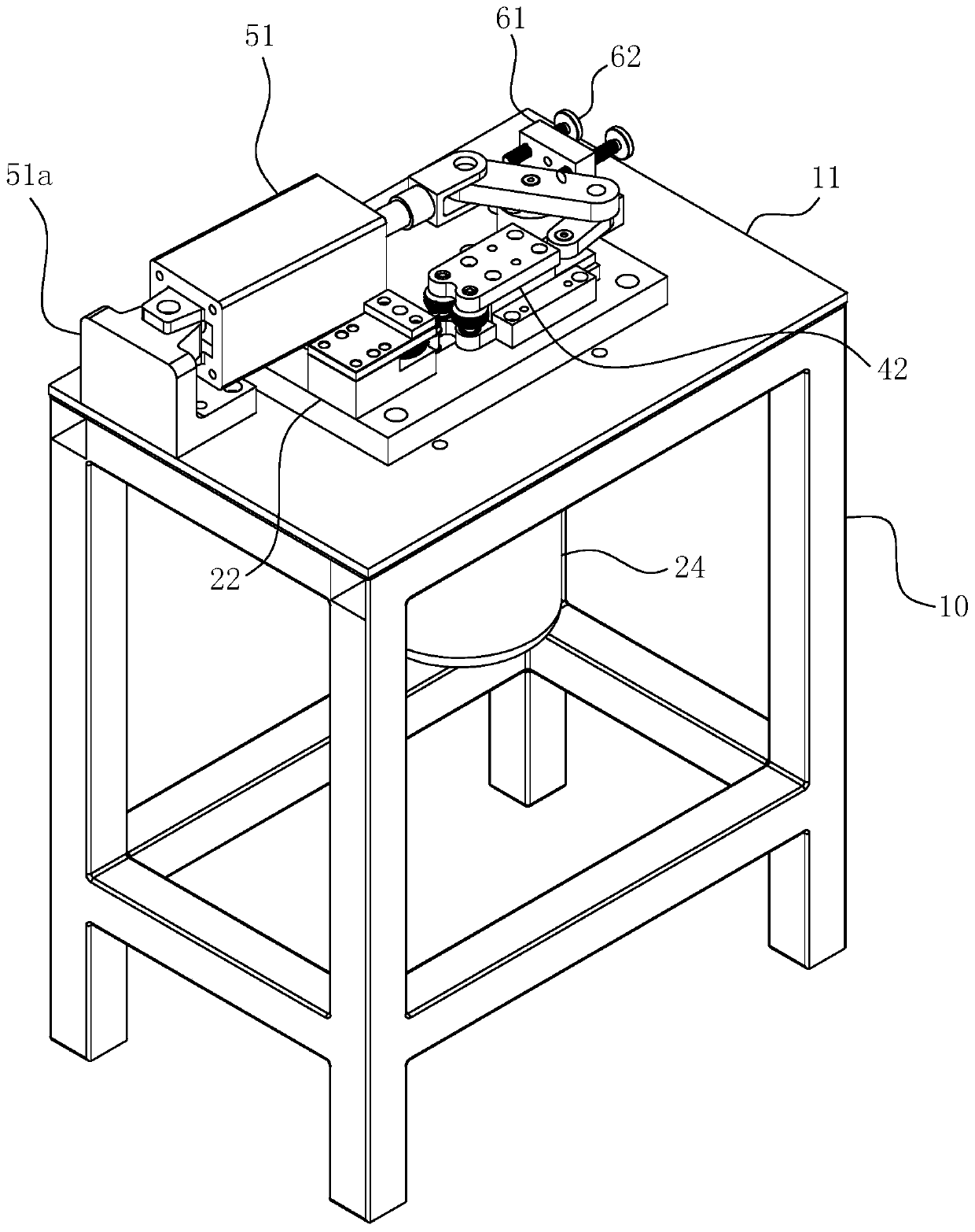
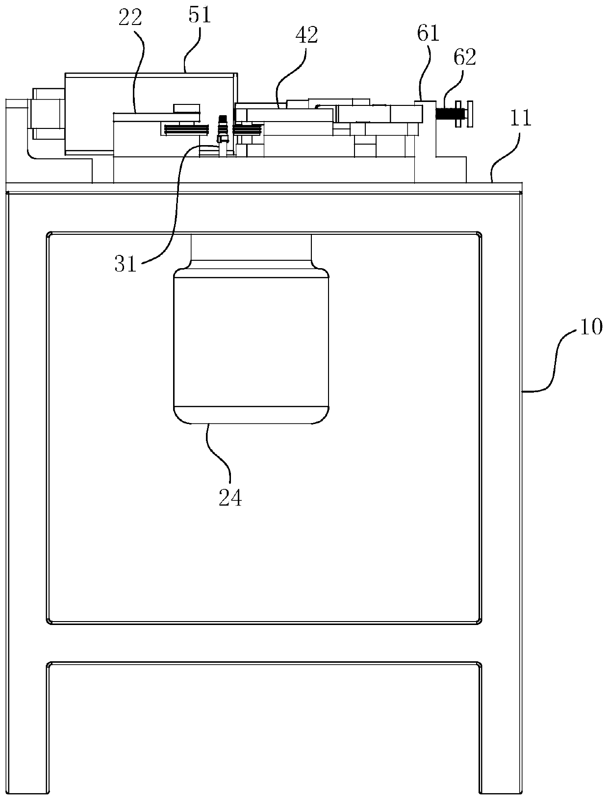
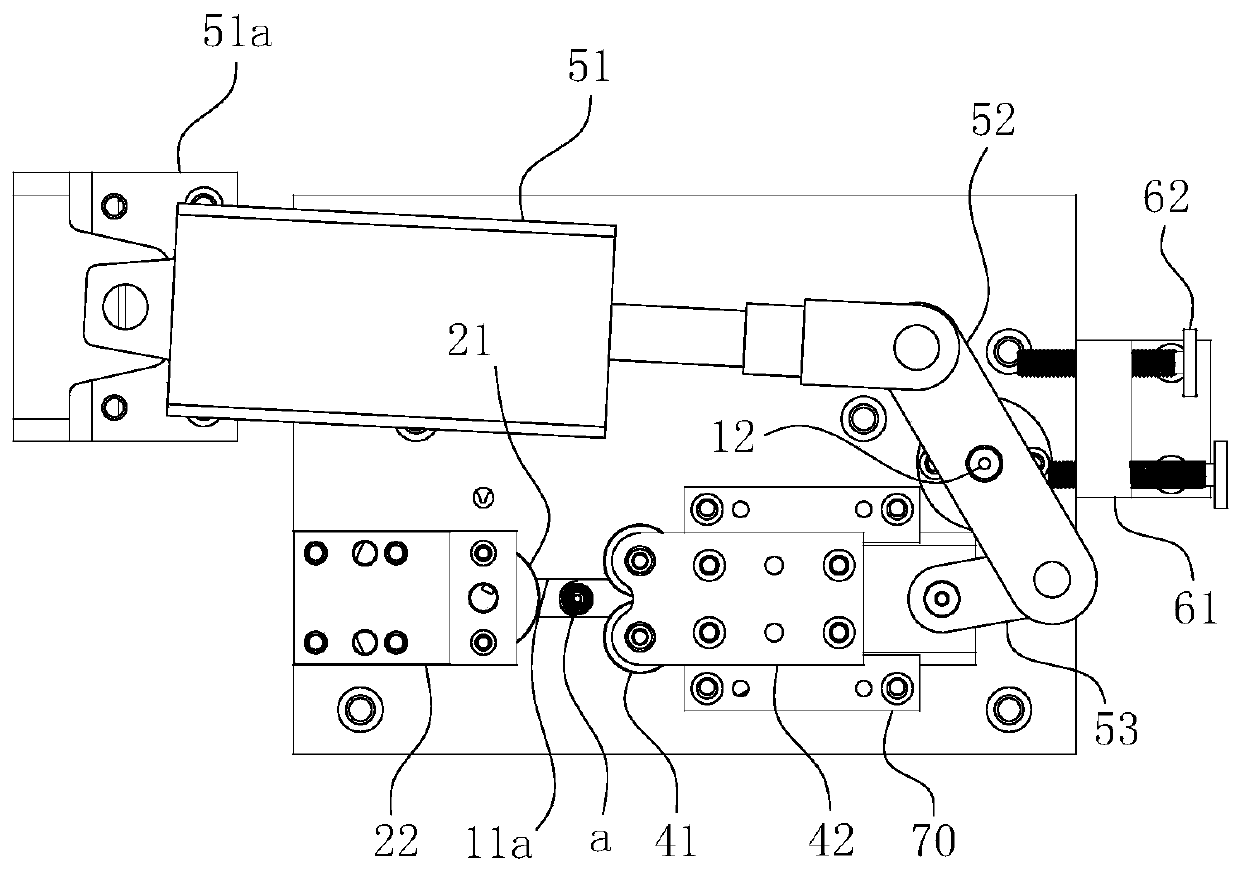
[0042] The specific structure of the present invention is as Figure 1-8 As shown, it includes a frame 10 with a work surface 11, a fixed knife mounting seat 22 for fixing the driving wheel 21, a moving knife mounting seat 42 for fixing the driven wheel 41, a slide block 33 for fixing the support body 31 and The air cylinder 51 etc. used to push the movable knife mounting seat 42 to produce directional movement. in:

[0043] The frame 10 can have various shapes, and its function is to provide a bearing surface, that is, a work surface 11, so as to facilitate the placement of various working parts. The fixed knife mounting seat 22 is directly as Figure 1-8 The shown is fixed on the work surface 11. In actual operation, the fixed knife mounting seat 22 can be split into two parts, the upper block and the lower bl...


PUM


Abstract

The invention belongs to the technical field of powder metallurgy, and particularly relates to an angle valve rod joint line removing device. The device comprises a rack with a working table; a driving wheel is arranged on the working table; and a supporting body is arranged beside the driving wheel and can do linear reciprocating motion relative to the driving wheel. The device further comprisesa driven wheel, and the driven wheel can perform approaching and departing actions relative to the driving wheel along the advancing path of the supporting body. The wheel groove contour curves of thedriving wheel and the driven wheel are matched with the contour curve of the annular installation groove of the workpiece, and when the driven wheel conducts approaching action relative to the driving wheel, the driving wheel and the driven wheel can jointly press the workpiece located on the supporting body in the radial direction in an opposite mode. Thus, the complete removal of the joint linecan be ensured, and meanwhile, the problem of excessive polishing cannot be generated, so that the product quality is greatly improved, and the water leakage risk caused by the joint line is eliminated.

Description

technical field [0001] The invention belongs to the technical field of powder metallurgy, and in particular relates to a device for removing mold line of an angle valve stem. Background technique [0002] The traditional angle valve stem is produced by machining, and there is no problem with the parting line; but with the development of social science and technology, many manufacturers have begun to use more advanced powder injection molding technology to produce angle valve stems. The powder injection molding process is the same as the plastic injection molding, which uses mold molding. Mold molding requires a parting surface, so there is inevitably a mold line problem. The stem of the angle valve is a rotary-shaped seal, and an annular installation groove is reserved for the installation of the sealing ring; if there is a parting line in the annular installation groove, it will inevitably affect its sealing performance, resulting in water leakage, which will seriously Aff...

Claims


Application Information

Patent Timeline
Patent Type & Authority Applications(China)
IPC IPC(8): B23P9/02
CPCB23P9/02
Inventor 欧阳其旺冉申谢松王嵩刘芸汪理健
Owner HEFEI HUIZHI NEW MATERIAL TECH CO LTD
Learn More