Grinding Monitoring Method Based on Thermal-Mechanical Coupling

A heat-mechanical coupling and grinding technology, which is applied in the direction of automatic grinding control devices, grinding machine parts, grinding/polishing equipment, etc., can solve the problem of large fluctuations in grinding temperature and grinding force, falling off, and affecting grinding Surface quality and other issues to achieve the effect of ensuring the grinding quality

Active Publication Date: 2021-07-02
HUAQIAO UNIVERSITY
View PDF9 Cites 0 Cited by
  • Summary
  • Abstract
  • Description
  • Claims
  • Application Information

AI Technical Summary

Problems solved by technology

[0003] During the grinding process, the grinding temperature and grinding force are different under different grinding parameters. Higher grinding temperature and grinding force will damage the grinding wheel and grinding parts, and the grinding temperature and grinding force Large fluctuations will also affect the surface quality of the grinding parts. Moreover, with the increase of the grinding time, the abrasive grains of the grinding wheel will appear blunt and fall off, and the grinding temperature and grinding force will also change accordingly, which will make the grinding wheel The dimensional accuracy and surface quality of the processed grinding parts are seriously affected. If the grinding wheel is not repaired or replaced in time, the product rejection rate will increase. Therefore, it is necessary to understand the state of the grinding wheel surface in real time and adjust the grinding parameters and replace the grinding wheel in time. Or it is necessary to dress the grinding wheel

Method used


Image

  • Grinding Monitoring Method Based on Thermal-Mechanical Coupling
  • Grinding Monitoring Method Based on Thermal-Mechanical Coupling
  • Grinding Monitoring Method Based on Thermal-Mechanical Coupling

Examples


Embodiment Construction

[0037] In order to further explain the technical solution of the present invention, the present invention will be described in detail below through specific examples.

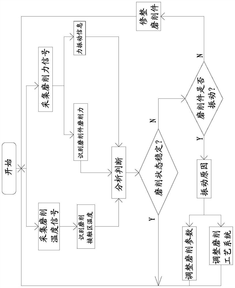
[0038] A grinding monitoring method based on thermal-mechanical coupling, such as Figure 1-4 shown, including the following steps:

[0039] A1: Setting the threshold: determine the grinding force threshold for grinding cracks, the temperature threshold for burns on the surface of the grinding part, and the fluctuation threshold for vibration of the grinding part:

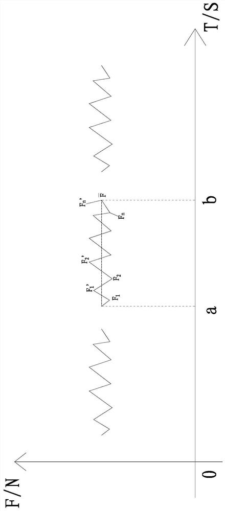
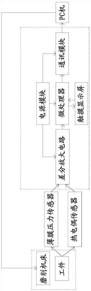
[0040] A2: Collecting information of grinding parts: during the grinding process of grinding parts, the grinding temperature signals are collected at intervals per unit time, and the grinding signals collected per unit time form a temperature signal set, and then every Collect the generated grinding force signals at intervals, and the collected grinding force signals per unit time form a force signal set;

[0041] A3: Obtain the grinding piece dat...


PUM


Abstract

The invention discloses a grinding monitoring method based on thermomechanical coupling, which is applied to a grinding machine tool and comprises the following steps: setting a threshold, collecting grinding piece information, acquiring grinding piece data, analyzing and judging, and analyzing vibration conditions; Compared with the existing technology, through the comprehensive analysis of the grinding temperature signals of the grinding parts, the grinding force signals of the force signals and the force vibration information, the grinding parts can be identified when the grinding parts are processed. Grinding state and vibration situation, so as to remind the operator, the operator makes corresponding operations according to the reminder, so as to monitor the grinding state of the grinding piece in real time and adjust it in time to ensure that the grinding piece is in a stable state during grinding. Thereby ensuring the grinding quality of the grinding parts.

Description

technical field [0001] The invention relates to the field of grinding monitoring, in particular to a coupling-based grinding monitoring method. Background technique [0002] Grinding is one of the important technologies to improve the surface quality of grinding parts. Many precision parts need to use grinding wheels for grinding and ultra-precision machining, and the degree of wear passivation of grinding wheels has an important impact on the surface quality of grinding parts. [0003] During the grinding process, the grinding temperature and grinding force are different under different grinding parameters. Higher grinding temperature and grinding force will damage the grinding wheel and grinding parts, and the grinding temperature and grinding force Large fluctuations will also affect the surface quality of the grinding parts. Moreover, with the increase of the grinding time, the abrasive grains of the grinding wheel will appear blunt and fall off, and the grinding tempera...

Claims


Application Information

Patent Timeline
Patent Type & Authority Patents(China)
IPC IPC(8): B24B1/00B24B55/00B24B51/00B24B49/10G05B19/042G01D21/02
CPCB24B1/00B24B49/10B24B51/00B24B55/00G01D21/02G05B19/0428
Inventor 尤芳怡汪旋洪健
Owner HUAQIAO UNIVERSITY
Why Eureka
Try Eureka