Eureka AIR delivers breakthrough ideas for toughest innovation challenges, trusted by R&D personnel around the world.

Automatic inflatable floating platform capable of being airdropped

A floating platform and automatic inflation technology, which is applied in the direction of inflatable life-saving equipment, sea and air rescue equipment, ships, etc., can solve the problems of floating platform stability and large space occupied by floating platforms, and achieve miniaturization of structural design and good floating stability Effect

Pending Publication Date: 2020-04-17
AEROSPACE LIFE SUPPORT IND LTD
View PDF0 Cites 1 Cited by
  • Summary
  • Abstract
  • Description
  • Claims
  • Application Information

AI Technical Summary

Problems solved by technology

[0005] Technical purpose of the present invention: the present invention designs an air-dropped automatic inflatable floating platform, which solves the problem of the stability of the floating platform in harsh environments and the problem that the space occupied by the floating platform in the air-dropped rescue unit is relatively large, and can be automatically inflated The body can be quickly put into use, bringing convenience to rescue operations at sea, improving the efficiency of rescue operations, and laying the foundation for subsequent rescue operations

Method used

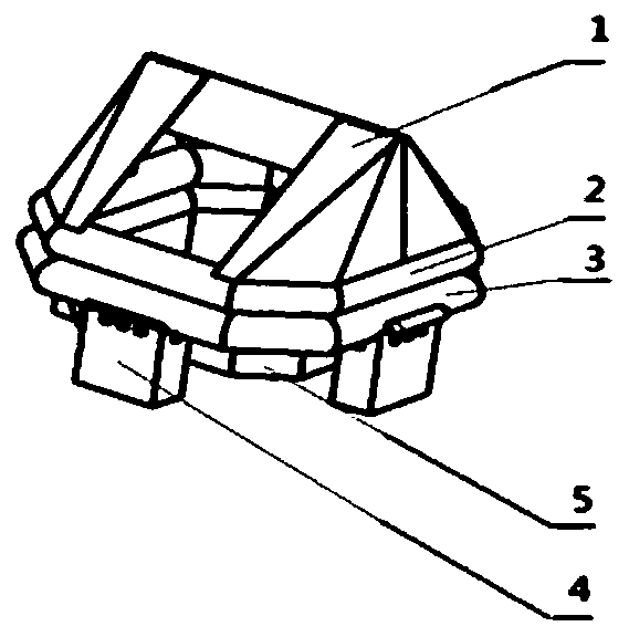

Image

  • Automatic inflatable floating platform capable of being airdropped
  • Automatic inflatable floating platform capable of being airdropped
  • Automatic inflatable floating platform capable of being airdropped

Examples


Embodiment Construction

[0019] The present invention will be described in further detail below by means of specific embodiments:

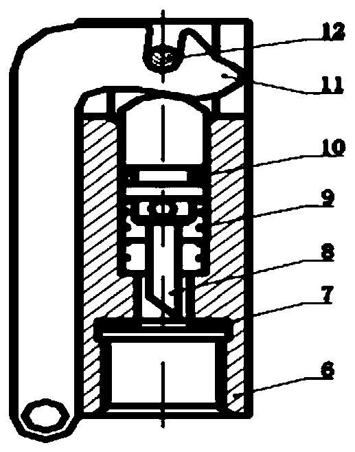
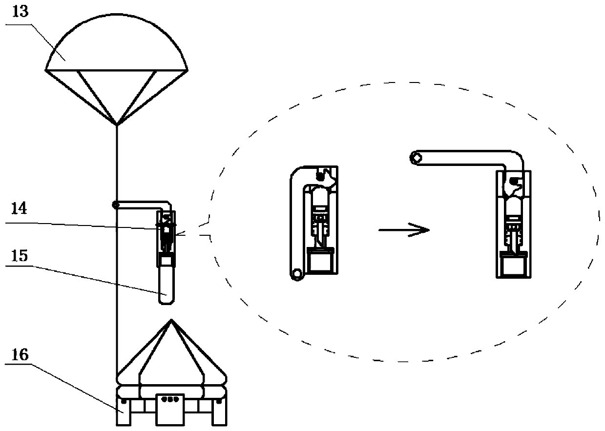
[0020] see Figure 1 to Figure 3 , a self-inflating floating platform that can be air-dropped, including a hull, a gas cylinder, and an inflation device 14, the hull, including a buoy, a boat canopy 1, a column, a bottom 5 and a water bag 4, and the buoys include upper buoys that are used as spares for each other 2 and the lower buoy 3 to ensure the buoyancy and stability of the floating platform, and at the same time to ensure that after one of the buoys is damaged, the other buoy can still provide lifesaving functions; the column is connected to the upper buoy 2 for carrying the boat canopy 1 Realize the functions of windshield, rain and sunshade, water collection and observation of the floating platform; the boat canopy 1 is connected to the column with a single buckle brocade ribbon; the bottom of the boat is deep, so that the user sits on the bottom 5 of the boat and...


PUM


Abstract

The invention provides an automatic inflatable floating platform capable of being airdropped. The platform comprises a ship body, a gas cylinder and an inflating device. The ship body comprises buoys,a boat awning, stand columns, a boat bottom and a water bag, wherein the stand columns are connected to the buoys and the boat awning is connected to the stand columns. The inflating device comprisesjoints, an inflating valve body, a striker, a spring, a rocker arm and a cylindrical pin, wherein the gas cylinder is screwed at the lower part of the striker of the inflating valve body; the two joints are arranged on the left side and the right side of the inflating valve body and are screwed with one end of each gas inlet pipe; the other ends of the gas inlet pipes are connected with the upperbuoy and the lower buoy of the ship body respectively; one end of the rocker arm is connected with a main umbrella system; the other end of the rocker arm is clamped between the cylindrical pin and the striker and can rotate around the cylindrical pin to push the striker to move to break through a diaphragm of the gas cylinder valve; after the air-drop lifesaving unit is started in the air, the upward movement tension of the main parachute system pulls off the rocker arm in a rotating mode, the rocker arm pushes the firing pin to move downwards in the rotating process, the diaphragm of the gas cylinder valve is broken through, gas in the gas cylinder rushes out and enters the buoys through the joints and the gas inlet pipes, and the floating platform is unfolded and formed to generate buoyancy.

Description

technical field [0001] The invention belongs to the field of marine lifesaving, and relates to a small-sized high-wave resistance floating platform for airdropping, in particular to an airdropping automatic inflatable floating platform. Background technique [0002] Floating platforms are mainly used for sea rescue, and are composed of hulls, carbon dioxide gas cylinders, inflatable devices, accessories, etc. Due to their good strength, airtightness, inflatability, and stability, the floating platforms have been widely used in various marine lifesaving fields . [0003] The existing floating platform has a large volume and a large number of people on board. It can only resist the third-level sea state. It is manually started and can only be used alone in offshore rescue. [0004] To sum up, the problems existing in the prior art are that due to the independent packaging and single use, they cannot be put into rescue quickly; the number of people on board is large, the hull ...

Claims


Application Information

Patent Timeline
IPC IPC(8): B63C9/02B63C9/01
CPCB63C9/02B63C9/01B63C2009/0029
Inventor 胡天鑫谷庆风李名琦万曲马启明文吉标高飞梁伟成
Owner AEROSPACE LIFE SUPPORT IND LTD
Why Eureka
Eureka Blog
Learn More