
Digital controlled lathe for processing piston with non-circular section

A CNC lathe, non-circular section technology, applied in the field of CNC lathes, can solve problems such as error, column needs to consider the gravity balance mechanism, complex structure, etc., to achieve the reduction of inertia, lightweight tool holder structure design, and small piston length-to-diameter ratio Effect

Inactive Publication Date: 2012-03-21
JIANGSU UNIV OF SCI & TECH
View PDF2 Cites 1 Cited by
  • Summary
  • Abstract
  • Description
  • Claims
  • Application Information

AI Technical Summary

Problems solved by technology

The utility model patent "A linear motor-driven CNC machine tool feed mechanism" (ZL200520139616.3) provides a CNC lathe feed mechanism that can be used for non-circular piston turning, and the paper "Open CNC system based on PMAC piston lathe" ("Mechatronics" magazine 2006.1 issue) such as figure 2 Shown is a piston lathe based on a traditional lathe structure. The linear motor of this lathe structure not only needs to complete small displacement and high-speed reciprocating feed motion, but also needs to adapt to the stroke adjustment requirements of the diameter of the processed piston. Rough machining of circular sections is done, so two installations introduce error
However, due to the vertical movement of the tool holder for feeding, the gravity balance mechanism of the column needs to be considered, and the structure is more complicated.

Method used


Image

  • Digital controlled lathe for processing piston with non-circular section
  • Digital controlled lathe for processing piston with non-circular section
  • Digital controlled lathe for processing piston with non-circular section

Examples


Embodiment

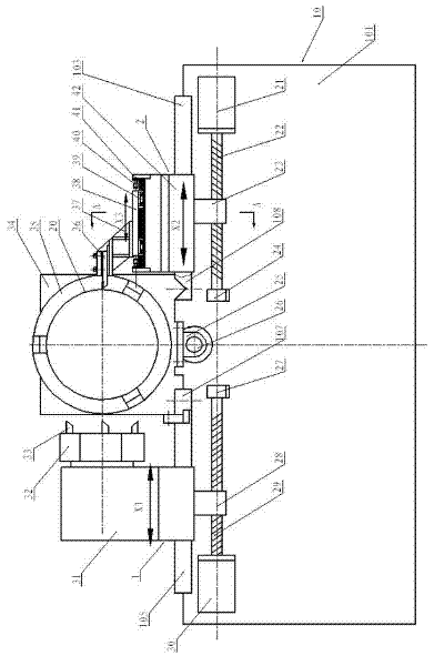
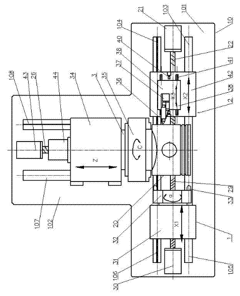
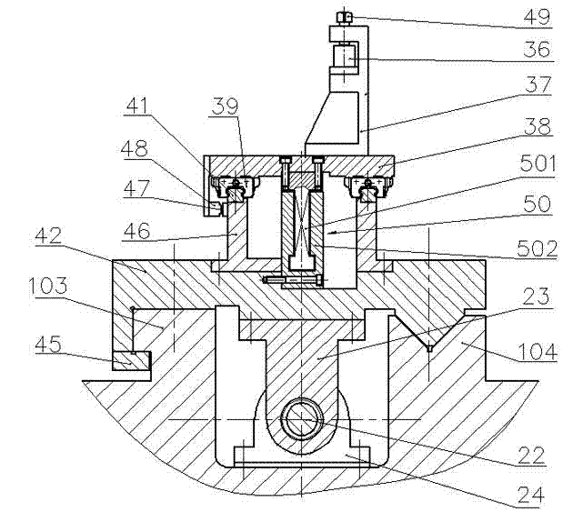
[0023] Example: attached figure 1 is the front view of the machine tool, attached figure 2 for figure 1 The top view, which expresses the contour shape of the so-called inverted "T"-shaped piston CNC lathe. The bed 10 is composed of a front bed 101 and a rear bed 102; the headstock 34 is installed on the rear flat guide rail 107 and the rear V guide rail 108 of the rear bed 102, and the main movement (C axis) of the machine tool is fixedly connected with the headstock Driven by the servo motor 44 of 34, the Z-axis feed motion along the axis of the piston 20 is driven by the Z-axis servo motor 43 to rotate the ball screw 26 and drive the spindle box 34 along the straight line of the rear flat guide rail 107 and the rear V guide rail 108 through the nut seat 25 Movement; the radial X-axis feed along the piston 20 is divided into three independent drives of the X1 axis, the X2 axis and the X3 axis, wherein the X1-axis feed is driven by the X1-axis servo motor 30 and the X1-ax...


PUM


Abstract

The invention discloses a digital controlled lathe for processing a piston with a non-circular section, and the body of the digital controlled lathe is in an inverted T-shaped structure, namely the body thereof is in a horizontal non-circular piston digital controlled lathe structure in which the principal shaft of a workpiece is horizontally rearmounted, and a left knife rest and a right knife rest are arranged on the front side, thus not only facilitating processing of the piston with the non-circular section and but also having the function of processing the circular section. Non-circular turning is realized by adopting a bilayer dual-drive structure, a linear electric motor is adopted for driving at an upper layer so as to realize feed motion of high-speed non-circular section turningwith small displacement, a servo motor and a ball screw nut mechanism are adopted for adjusting the changed diameter of the processed piston at a lower layer, and the rough machining and finishing machining are integrated into a whole so as to enable the piston processing mode to be more reasonable, convenient and efficient.

Description

technical field [0001] The invention relates to a cutting machine tool, in particular to a numerically controlled lathe for machining non-circular cross-section pistons. Background technique [0002] Ordinary lathes (including CNC lathes) can only turn workpieces with circular cross-sections, while some parts require non-circular cross-sections, such as internal combustion engine pistons, which are generally cast aluminum or cast iron materials, which will be deformed by mechanical and thermal loads during work, such as The pistons of medium and high-speed diesel engines used in ships have high temperature during operation, and this deformation is particularly obvious. Since the piston must be provided with a boss at the piston pin, the material inside the piston is distributed irregularly. When the piston is heated and expands during operation, its outer surface expands irregularly, and the maximum expansion occurs along the piston pin axis. Therefore, in order to mak...

Claims


Application Information

Patent Timeline
Patent Type & Authority Patents(China)
IPC IPC(8): B23B21/00B23B5/00B23Q5/40B23B17/00
Inventor 张冰蔚朱鹏程邱必稳刘汉平
Owner JIANGSU UNIV OF SCI & TECH
Learn More