Rapid fluorescence lifetime imaging system and method for flow field diagnosis

A fluorescence lifetime, imaging system technology, applied in fluorescence/phosphorescence, fluid dynamics test, machine/structural component testing, etc. It can overcome the problems of slow imaging speed, fast imaging speed and high frame rate, etc.

Pending Publication Date: 2020-04-17
XI'AN INST OF OPTICS & FINE MECHANICS - CHINESE ACAD OF SCI
View PDF1 Cites 4 Cited by
  • Summary
  • Abstract
  • Description
  • Claims
  • Application Information

AI Technical Summary

Problems solved by technology

[0007] In order to solve the technical problems that the existing fluorescence imaging technology is slow, the measurement accuracy of fluorescence lifetime is low, and it cannot meet the requ

Method used


Image

  • Rapid fluorescence lifetime imaging system and method for flow field diagnosis
  • Rapid fluorescence lifetime imaging system and method for flow field diagnosis
  • Rapid fluorescence lifetime imaging system and method for flow field diagnosis

Examples


Embodiment Construction

[0050] The content of the present invention will be further described in detail below in conjunction with the accompanying drawings and specific embodiments.

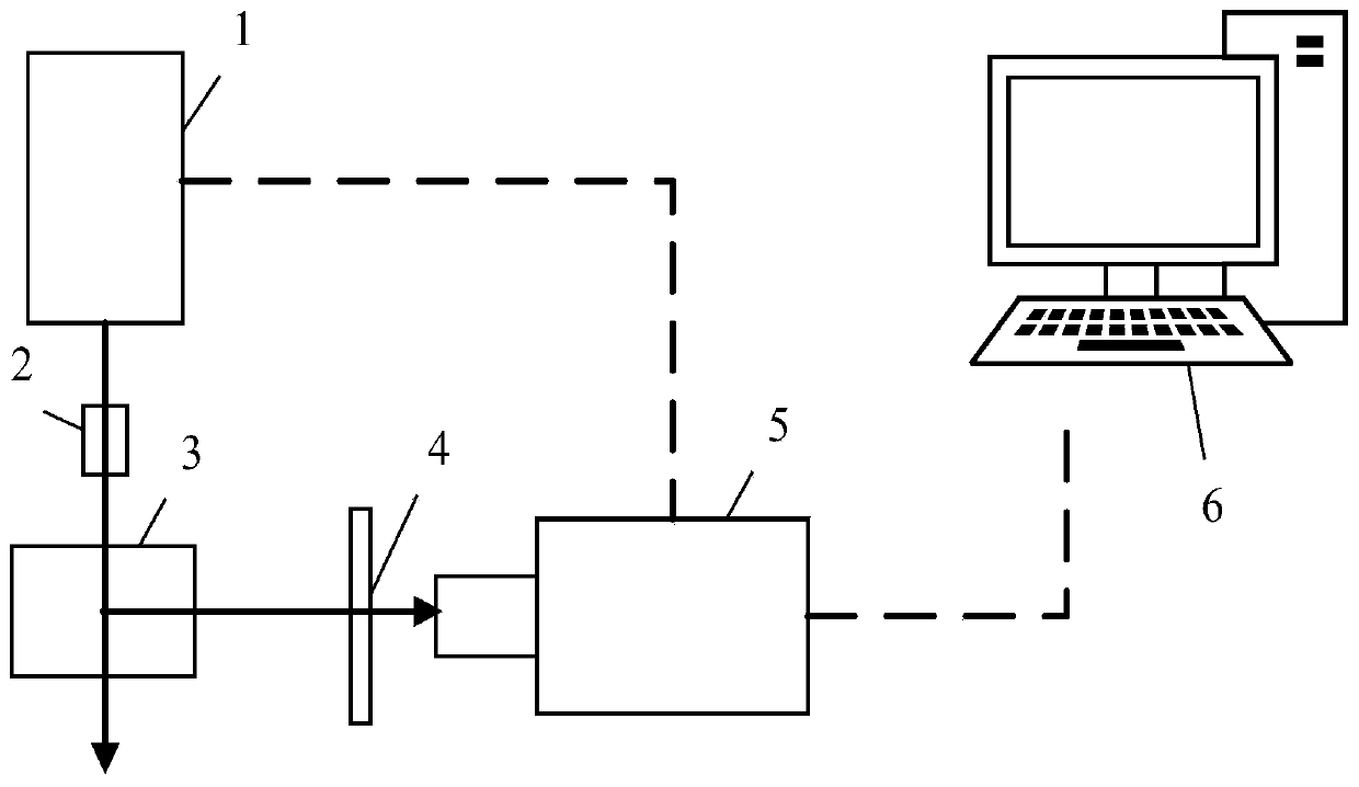
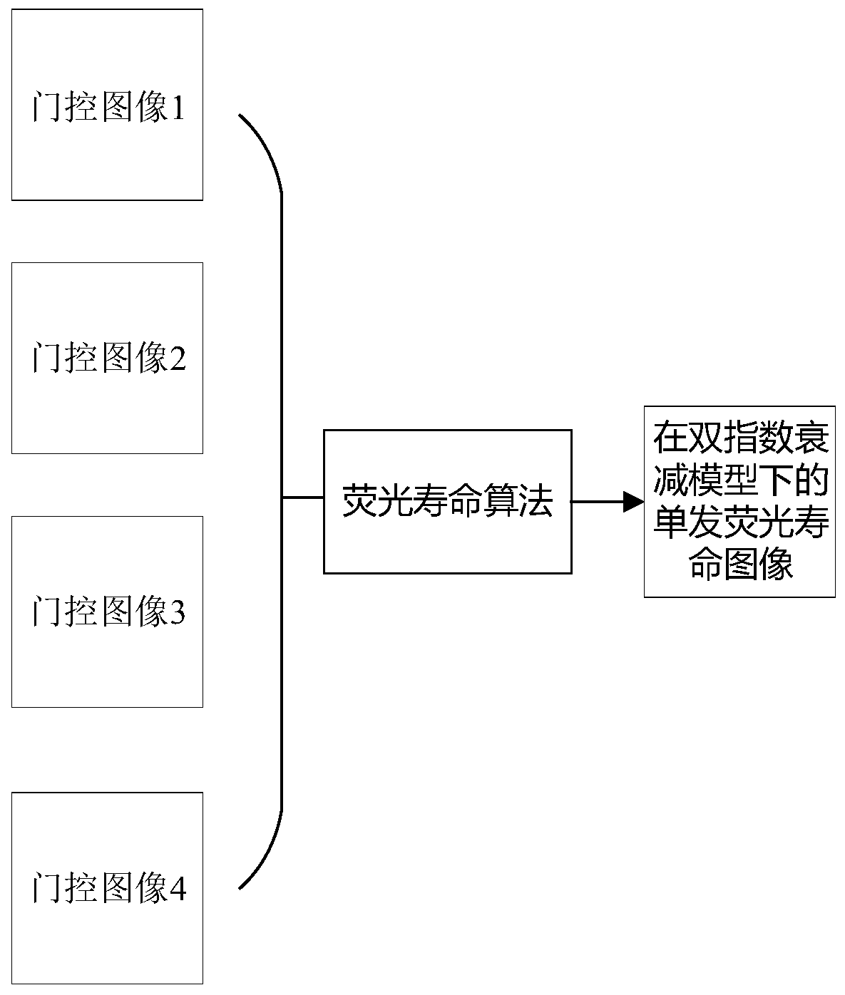
[0051] Such as figure 1 As shown, a fast fluorescence lifetime imaging system for flow field diagnosis includes a pulsed laser 1 , a sheet light shaping device 2 , a flow field generating device 3 , a filter 4 , a framing camera 5 and a data processing device 6 .

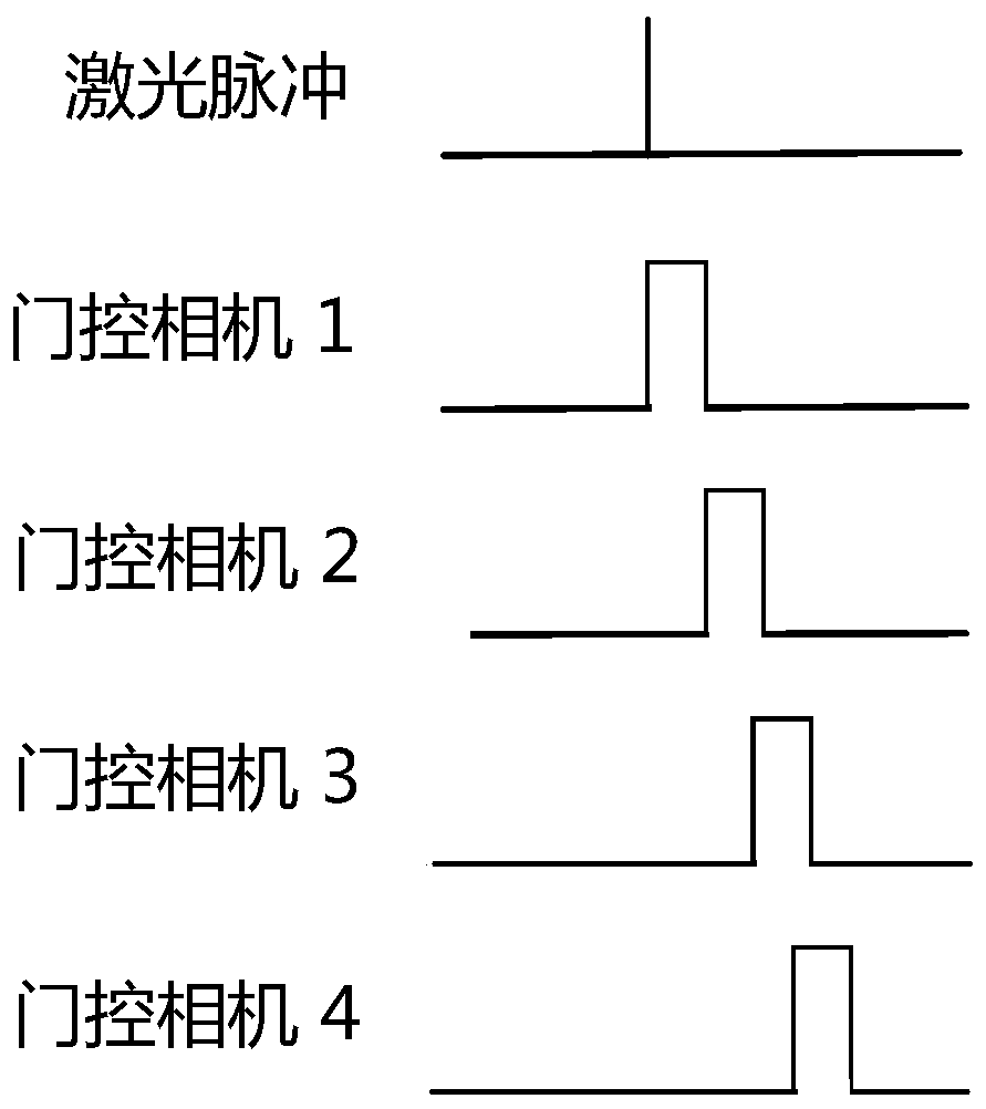
[0052] The pulse laser 1 generates a picosecond laser pulse whose energy is in the millijoule level of a single pulse and whose wavelength is at the absorption peak of the target component, and is used to excite the target flow field generated by the flow field generating device 3; at the same time, the pulse laser 1 emits an electric current The signal is used to trigger the framing camera 5 to perform exposure.

[0053] The sheet light shaping device 2 is used to shape the laser pulse into a sheet of light to realize wide-field imaging of the flow field. I...


PUM


Abstract

The invention provides a rapid fluorescence lifetime imaging system and method for flow field diagnosis, and solves the problems of low imaging time resolution and low frame rate of the existing fluorescence lifetime imaging technology. The system comprises a pulse laser, a sheet light shaping device, a flow field generating device, a filter, a framing camera and a data processing device, the pulse laser emits laser pulses and electric signals at the same time, and the sheet light shaping device is used for shaping the laser pulses into sheet light. The flow field generating device is used forproviding a to-be-detected target flow field, and the to-be-detected target flow field emits a fluorescence signal after being irradiated by sheet light; the filter is used for transmitting the fluorescence signal and filtering a spurious signal; the framing camera comprises a synchronous control device and four gating cameras, and the synchronous control device controls exposure time gates and delays of the four gating cameras; the electric signals trigger the framing camera to expose to obtain a four-framing image; and the data processing device is used for receiving the four-framing imagecaptured by the framing camera and processing the four-framing image to obtain a fluorescence lifetime image and displaying the fluorescence lifetime image.

Description

technical field [0001] The invention relates to flow field diagnosis technology, in particular to a fast fluorescence lifetime imaging system and method for flow field diagnosis. Background technique [0002] The flow field includes air flow, combustion, plasma and multiphase flow field. The experimental research on the flow field diagnostic technology can provide data support for the establishment and verification of the flow field model, thereby providing a theoretical basis for the application of related projects, such as engine performance promote. Traditional flow field diagnosis techniques are mostly intrusive, which will disturb the flow field, resulting in errors in the measurement of flow field parameters. [0003] At present, the most advanced flow field diagnostic technology is optical diagnostic technology, which can realize non-invasive measurement of flow field; among them, planar laser-induced fluorescence lifetime imaging (PLIF) technology is widely used, wh...

Claims


Application Information

Patent Timeline
IPC IPC(8): G01N21/64G01M10/00
CPCG01M10/00G01N21/6456
Inventor 李亚晖高贵龙何凯田进寿
Owner XI'AN INST OF OPTICS & FINE MECHANICS - CHINESE ACAD OF SCI
Why Eureka
Try Eureka