Shunting method wireless charging circuit
A wireless charging and shunt circuit technology, applied in battery circuit devices, circuit devices, different battery charging, etc., can solve the problems of high battery quality and safety management requirements, fast charging time, etc., to improve charging efficiency and reasonable design structure , the effect of protecting the battery
- Summary
- Abstract
- Description
- Claims
- Application Information
AI Technical Summary
Problems solved by technology
Method used
Image

Examples
Embodiment 1
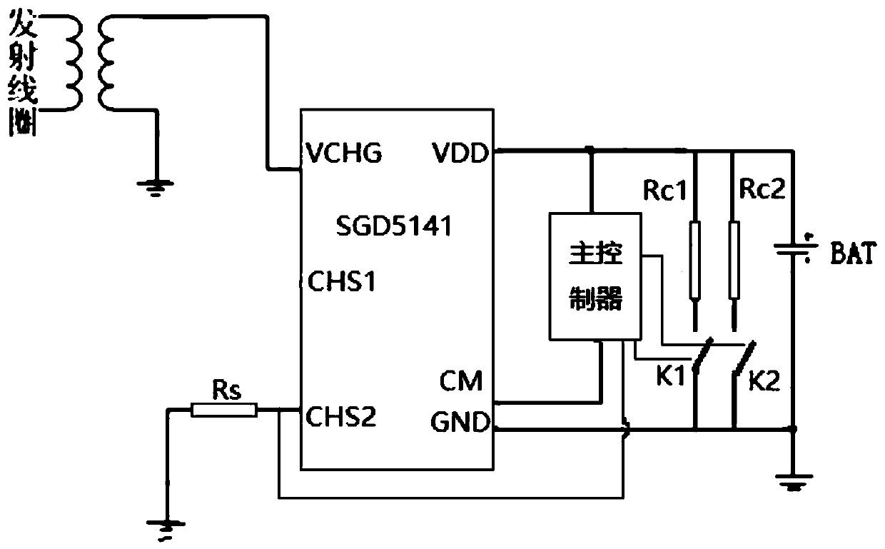
[0027] The wireless charging receiving chip adopts SGD5141 chip, VCHG pin: external wireless charging coil, the energy of electromagnetic coupling is input to this port; CHS2 pin: external LED or MCU IO, charging status indication; VDD pin: chip power positive, connected to the Rechargeable battery positive terminal; CM pin: load GND, built-in lithium battery over-discharge, over-current, short-circuit protection switch; GND pin: chip power ground, connected to the negative terminal of the rechargeable battery. The maximum constant current charging current is 120mA, and the minimum trickle current is 30mA; CM is the load GND, and the built-in switch for lithium battery over-discharge, over-current, and short-circuit protection. CHS2 can also provide charging status indication after an external LED is connected, 6Hz fast flashing: abnormal state, discharge overcurrent or short circuit occurs; 1Hz slow flashing, normal charging; always on: the battery is fully charged, on the cha...
Embodiment 2
[0029] The SGD5141 chip is set to output a constant current; when the main controller monitors that the battery voltage is less than the voltage lower threshold Vbl or greater than the voltage upper threshold Vbh, when trickle charging is required, the control switches K1 and K2 are closed, and the resistors Rc1 and Rc2 are turned on and shunted , the system charges the battery with a small current;
[0030] When the main controller detects that the battery voltage is greater than Vbl and less than Vbh, the control switch K1 or K2 is turned off, the resistor Rc1 or Rc2 is not turned on, and the system charges the battery with a larger current.
Embodiment 3
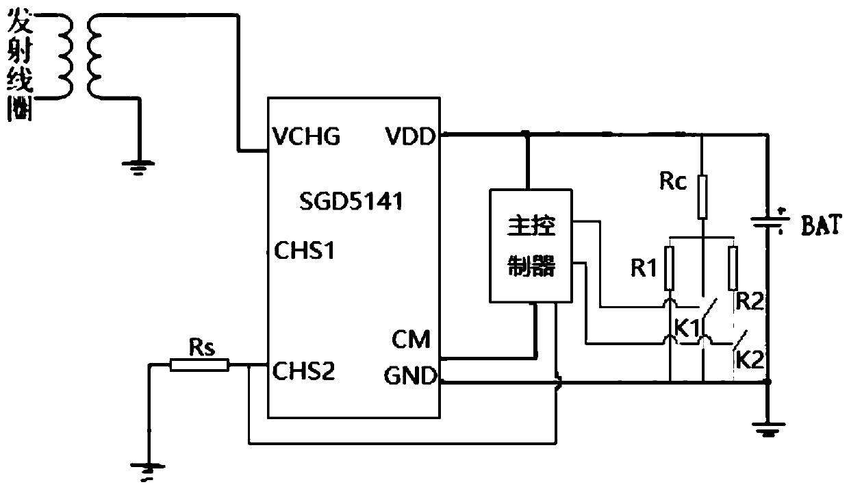
[0032] This embodiment charges the customized 10mAh micro-lithium battery, the minimum working current of the SGD5141 chip is 30mA, and the output current of the SGD5141 chip is designed to be 35mA by adjusting the coil size and distance; resistance Rc=90Ω; resistance R1=48Ω; resistance R2= 400Ω. When it is detected that the battery voltage is less than 2.7V, the control switch K1 is closed, 2.7V / 90Ω=30mA, and the battery charging current is 5mA.
[0033] When the battery voltage rises >2.7V, turn off the control switch K1, close the control switch K2, 3.3V / (90Ω+48Ω / / 400Ω)=25mA, and the battery charging current is 10mA.
[0034] When the battery voltage rises to 4.14V, turn off the control switches K1, K2, 4.15V / (90Ω+48Ω)=30mA, and the battery charging current is 5mA.
[0035] Stop charging when it detects that charging is complete.
PUM
 Abstract
Description
Claims
Application Information