Liquid discharge device, sensor manufacturing device having liquid discharge device, and cell culture device having liquid discharge device
A cell culture and sensor technology, applied in fluid controllers, laboratory containers, biochemical cleaning devices, etc., can solve the problems of performance degradation, inability to clean the liquid ejection head, and metal-free, etc., and achieve the goal of reducing waste loss Effect
- Summary
- Abstract
- Description
- Claims
- Application Information
AI Technical Summary
Problems solved by technology
Method used
Image

Examples
Embodiment approach 1
[0035]
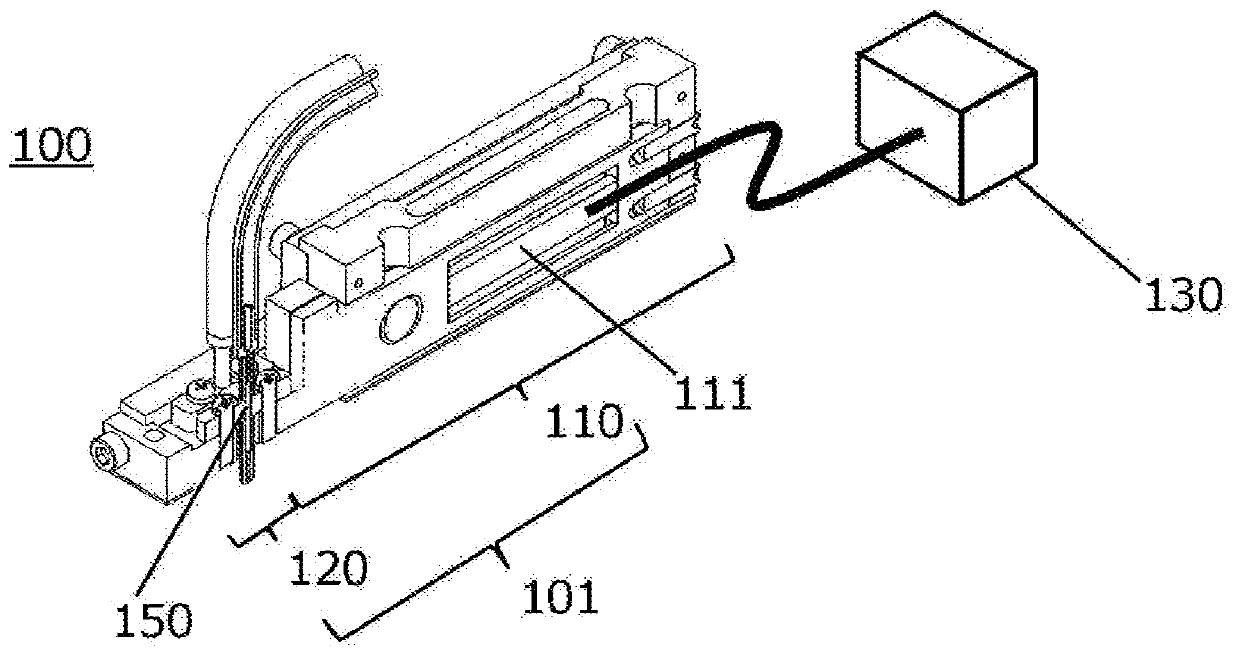
[0036] Figure 1A It is a schematic diagram showing the internal structure of the liquid ejection device according to Embodiment 1 of the present invention viewed obliquely from above. In the liquid ejection device 100 , the base body 101 has a driving portion 110 and a fixing portion 120 . The driving unit 110 is a part having a driving mechanism for pressurizing the nozzle 150 . The fixing part 120 is a part having a mechanism for fixing the nozzle 150 .
[0037] A piezoelectric element 111 that generates displacement is provided in the drive unit 110 . In synchronization with the drive pulse signal generated by the external waveform generator 130 , the piezoelectric element 111 is displaced telescopically. In the following, the piezoelectric element 111 will be used for description, but any mechanism other than the piezoelectric element 111 may be used as long as it is a mechanism that generates displacement.
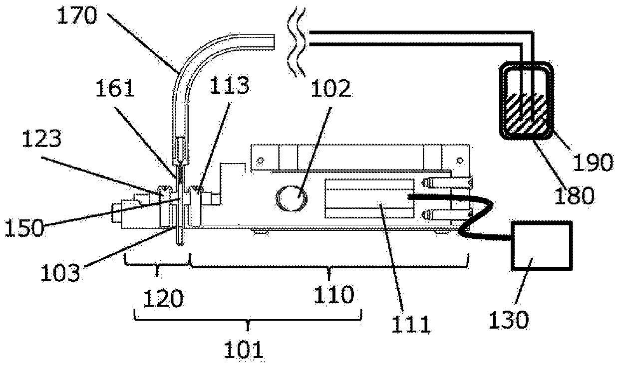
[0038] in addition, Figure 1B It is a schematic...
Embodiment approach 2
[0069]
[0070] Figure 5 It is a schematic diagram showing the cross-sectional structure of the liquid ejection device 200 in Embodiment 2 viewed from the side. Items not described are the same as those in Embodiment 1. The difference from Embodiment 1 is that the nozzle is pressurized and compressed from both sides.
[0071] The liquid ejection device 200 is equipped with a pair of driving parts 210 inside the base body 201 .
[0072] A piezoelectric element 211 that generates displacement is provided in the driving unit 210 . The piezoelectric element 211 expands and contracts in synchronization with the drive pulse signal generated by the external waveform generator 230 to generate displacement.
[0073] In addition, the drive unit 210 is fixed at the end of the base body 201 . In addition, the position of the drive unit 210 is held by the fixed rod 202 . The drive unit 210 inserted into the fixed rod 202 is processed to have an oblong shape whose major axis is the ...
Embodiment approach 3
[0085] Embodiment 3 is an application example of the liquid ejection devices 100 and 200 described above and the liquid ejection devices 700 and 900 described below. These devices are capable of applying a small amount of liquid with high precision and a constant amount over a long period of time.
[0086] Therefore, it can be used to apply blood to biosensors, biochips, and the like. For example, when applying blood to a blood sensor, the liquid ejection device 100, 200, 700, or 900 applies liquid droplets to the blood sensor, and the blood sensor is read by a detector to know the amount of blood. value. In this method, the accuracy of the volume of blood is good, and the result is correct.
[0087] Instead of a blood sensor, coating may be applied to an immunosensor for a tumor marker, a cardiac disease marker, or the like. Furthermore, the sensor may be a DNA sensor for epigenetics, infectious diseases, or the like. As sensors, biosensors can be widely used.
[0088] e...
PUM
 Abstract
Description
Claims
Application Information
 - R&D
- Intellectual Property
- Life Sciences
- Materials
- Tech Scout
- Unparalleled Data Quality
- Higher Quality Content
- 60% Fewer Hallucinations
Browse by: Latest US Patents, China's latest patents, Technical Efficacy Thesaurus, Application Domain, Technology Topic, Popular Technical Reports.
© 2025 PatSnap. All rights reserved.Legal|Privacy policy|Modern Slavery Act Transparency Statement|Sitemap|About US| Contact US: help@patsnap.com