Supercharge Your Innovation With Domain-Expert AI Agents!

Pulse type vibration deep scarification machine

A subsoiler and pulse-type technology, which is applied in the field of pulse-type vibratory subsoilers, can solve the problems of high energy consumption, increased contact between soil and air, and large differences, so as to expand the area of ​​soil lifting, improve the crushing effect, The effect of increasing the oxygen content

Pending Publication Date: 2020-04-21
内蒙古农业大学职业技术学院
View PDF0 Cites 2 Cited by
  • Summary
  • Abstract
  • Description
  • Claims
  • Application Information

AI Technical Summary

Problems solved by technology

[0003] There are two types of existing subsoilers. One is purely mechanical, which uses a subsoiler to cut through the bottom layer of the plow. The contact between the soil and the air is increased, so that the water absorbed by the soil evaporates faster, and at the same time, the oxygen content of the deep soil cannot be effectively improved; the other is the pneumatic type, which uses a gas generator to blow air into the deep soil to achieve loosening. soil effect, but in this way, when the air pressure tilts forward to hit the soil block, the tractor will have a serious dragging feeling, resulting in very high energy consumption, and the subsoiling effect is not obvious; because the above two types of subsoiling There is a large difference in the subsoiling effect of each height of the soil layer, so there is an urgent need for a subsoiler that can not only increase the soil oxygen content, but also ensure the same subsoiling effect at each height.

Method used


Image

  • Pulse type vibration deep scarification machine
  • Pulse type vibration deep scarification machine
  • Pulse type vibration deep scarification machine

Examples


Embodiment Construction

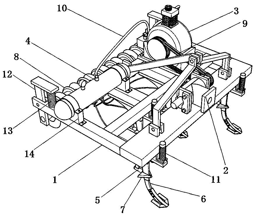
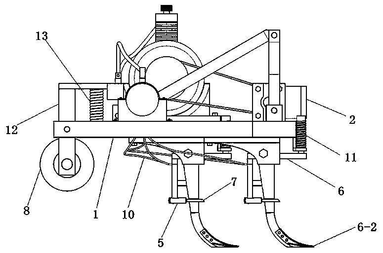
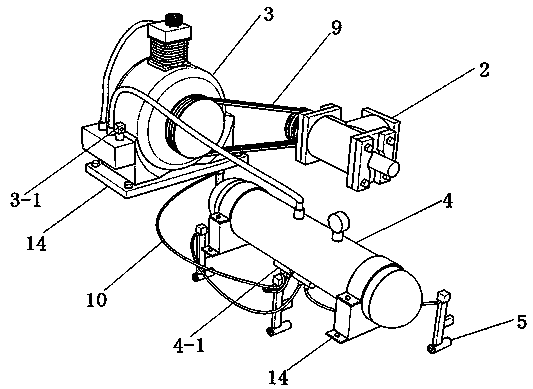
[0025] In order to enable those skilled in the art to better understand the technical solution of the present invention, the present invention will be further described in detail below in conjunction with the accompanying drawings. The following description is only used to illustrate the technical solution of the present invention and not limit it.

[0026] In describing the present invention, it is to be understood that the terms "center", "upper", "lower", "front", "rear", "left", "right", "top", "bottom", " The orientation or positional relationship indicated by "inner", "outer", etc. is based on the orientation or positional relationship shown in the drawings, which is only for the convenience of describing the present invention and simplifying the description, rather than indicating or implying that the referred device or element must have a specific orientation, are constructed and operate in a particular orientation and therefore are not to be construed as limiting the i...


PUM


Abstract

The invention discloses a pulse type vibration deep scarification machine. The pulse type vibration deep scarification machine comprises a machine frame, a commutator, an air compressor, an air storage tank, vibrators, deep scarification shovels, scarification wings and a soil pressing roller, wherein the commutator is arranged at the front end of the machine frame, the air compressor is arrangedon the machine frame, and the air compressor is connected with the commutator through a belt; the air storage tank is arranged on the machine frame, one end of the air storage tank is connected with the air compressor through an air transporting pipe, and the other end of the air storage tank is connected with the vibrators through air transporting pipes; the deep scarification shovels are hingedto the machine frame, a sliding chute is formed in a shovel handle of each deep scarification shovel, and each scarification wing is arranged in the corresponding sliding chute; a spring is arranged on the top surface of each deep scarification shovel; and the soil pressing roller is hinged to the rear end of the machine frame. According to the pulse type vibration deep scarification machine disclosed by the invention, the shovel heads at the bottom layer, the scarification wings at the middle layer and the soil pressing roller at the upper layer jointly act on soil, so that comprehensivenessof deep scarification soil can be guaranteed; and in addition, the springs cooperating with the deep scarification shovels can effectively evade resistance of high pressure air, and the power utilization rate is maximized.

Description

technical field [0001] The invention relates to the technical field of agricultural implements, in particular to a pulse type vibration subsoiler. Background technique [0002] Subsoil plowing is a method of deep plowing in which soil loosening tools such as subsoil shovels or chisel plows are used to loosen the soil without turning over the soil layer; the depth can reach more than 20 cm; it is suitable for forming the plow bottom layer after long-term plowing, and the plow layer has clay Hard or white pulp layer or land with thick soil layer and thin cultivated layer is not suitable for deep plowing; its function: ① break the plow bottom layer, white pulp layer or clay hard disk, deepen the cultivated layer and mature the subsoil, which is conducive to deep penetration of crop roots; ② does not turn over The soil layer and subsequent crops can make full use of the nutrients in the original plow layer, maintain the microbial flora, and reduce the inhibition of the anaerobic...

Claims


Application Information

Patent Timeline
IPC IPC(8): A01B35/12A01B35/24A01B35/20
CPCA01B35/12A01B35/20A01B35/24
Inventor 赵永来牛文学张旭翟鹏高伟王利鹤丁亚庆蔺建波刘志强康超张勇苗佳刘晓宇
Owner 内蒙古农业大学职业技术学院
Features
  • R&D
  • Intellectual Property
  • Life Sciences
  • Materials
  • Tech Scout
  • Unparalleled Data Quality
  • Higher Quality Content
  • 60% Fewer Hallucinations
Learn More