Airtightness detecting machine and method for electronic products
A sealing detection, electronic product technology, applied in liquid tightness measurement using liquid/vacuum degree, by measuring the increase and decrease rate of fluid, sorting and other directions, it can solve the problem of poor sealing of detection fixtures, poor detection effect, Low degree of automation and other problems, to achieve the effect of fast detection efficiency, good sealing, high degree of automation
- Summary
- Abstract
- Description
- Claims
- Application Information
AI Technical Summary
Problems solved by technology
Method used
Image

Examples
Embodiment 1
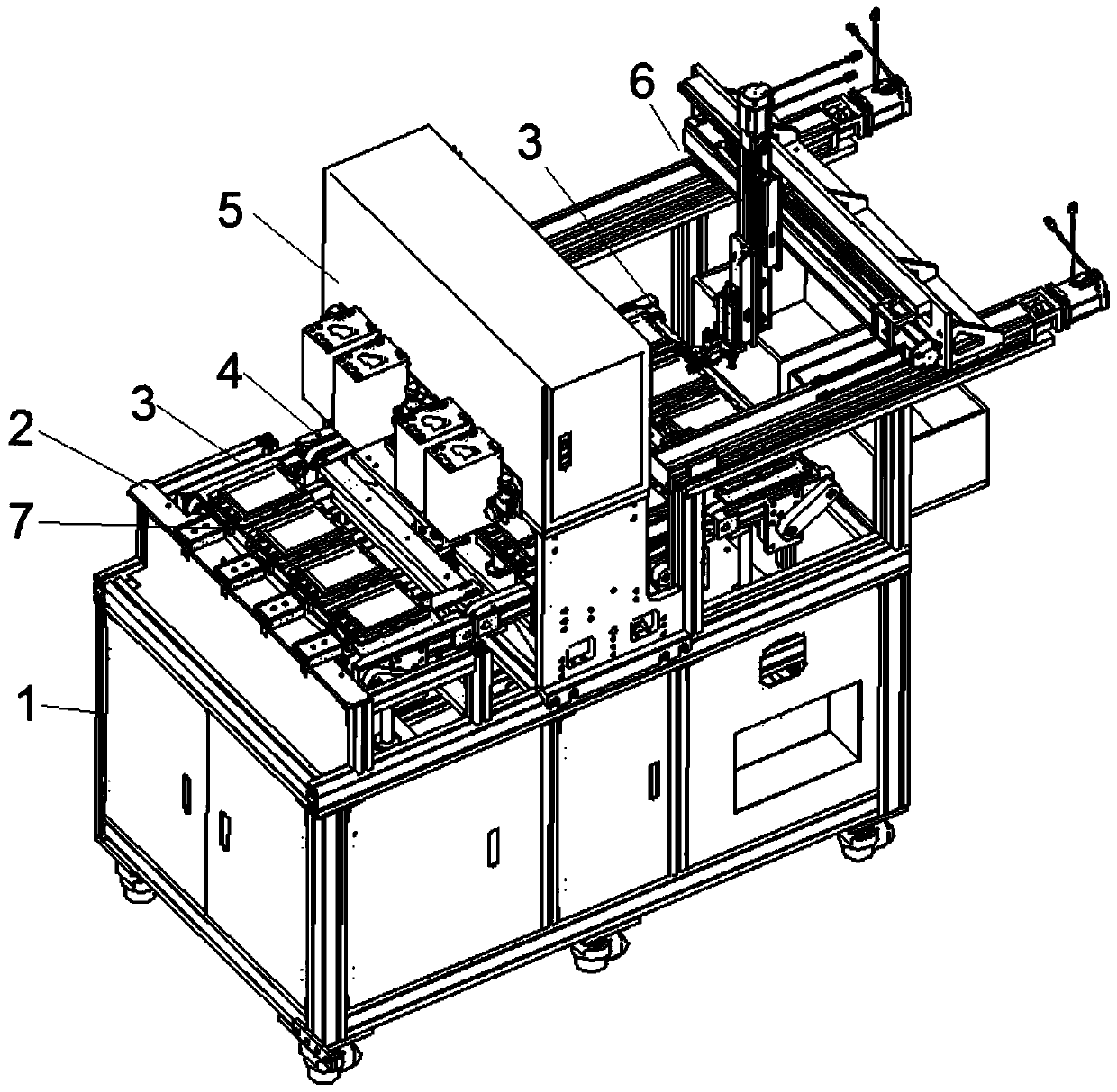
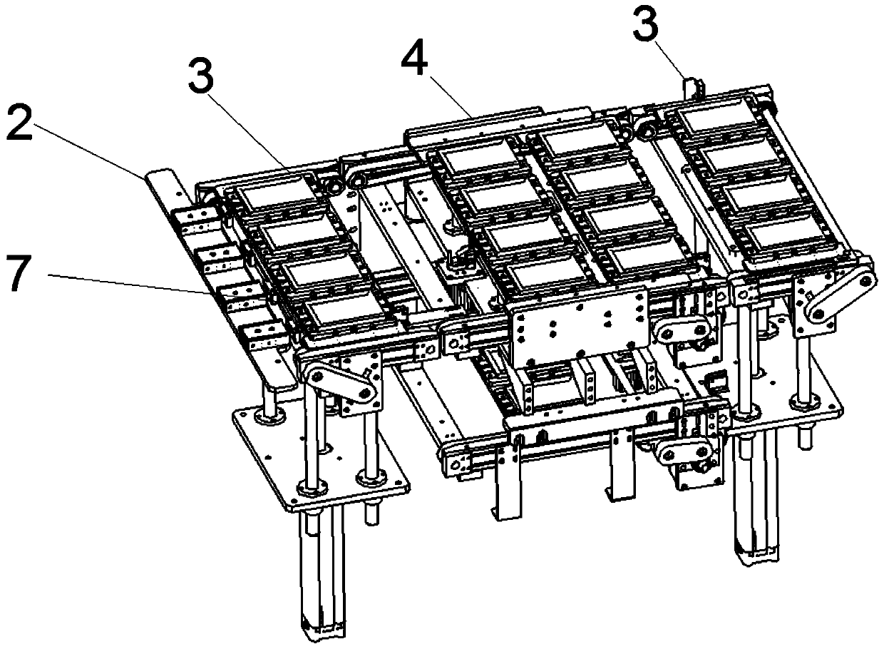
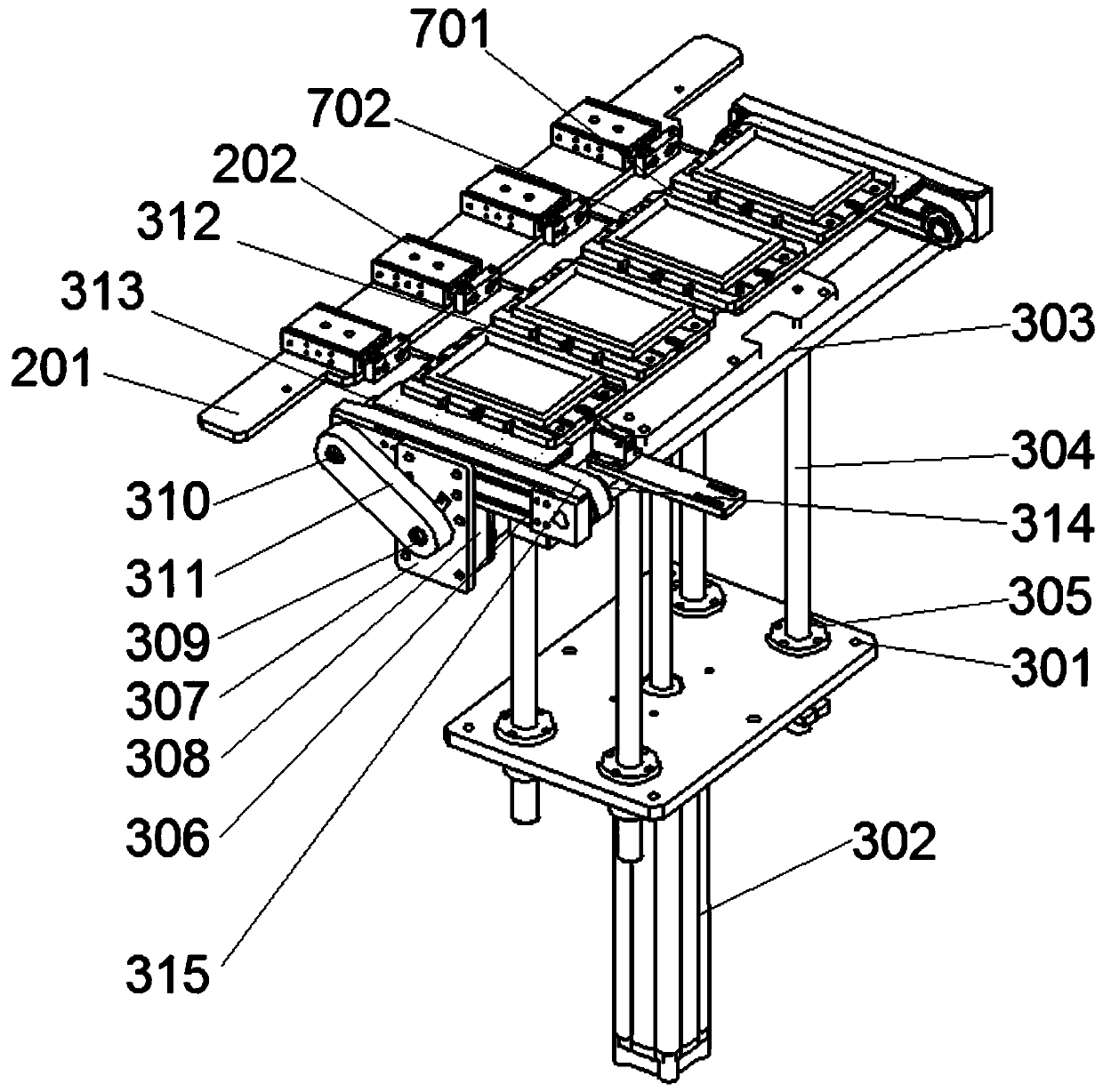
[0034] see Figure 1-8 , in an embodiment of the present invention, a leak detection machine for electronic products, including a frame 1 in contact with the ground, a support seat and rollers are arranged under the frame 1, which is convenient for moving and supporting, and the upper end surface of the frame 1 The left side is fixed with a pusher mechanism 2 by screws to assist the pusher mechanism. The right side of the pusher mechanism 2 is provided with a lifting conveyor belt 3, which lifts and conveys the jig, and the right side of the lifting conveyor belt 3 is provided with a loop The streamline 4 is used for the conveying and positioning of the jig. The circulating streamline 4 includes two conveying streamlines 401 up and down. The middle part of the upper conveying streamline 401 is equipped with a jacking positioning mechanism 402 to effectively position the jig. , the lifting conveyor belt 3 is arranged on the right side of the circulating flow line 4, and a seali...
Embodiment 2
[0039] The sealing detection mechanism 5 includes a U-shaped mounting base 501 fixed to the frame 1 by screws, and the U-shaped mounting base 501 is evenly distributed with four adjustable cylinders 502, and a detector is arranged in front of the adjustable cylinders 502. 503, the right side of the detector 503 is provided with a pressure regulating valve 504, the lower end of the adjustable cylinder 502 is connected with the pressing fixed plate 505, the pressing fixed plate 505 is connected with the guide rod C506 by screws, and the upper part of the guide rod C506 Slidingly connected with the linear bearing C507, the linear bearing C507 is connected with the U-shaped mounting seat 501 by screws, the lower end surface of the pressing and fixing plate 505 is connected with the detection fixture plate 508 by screws, and the outer side of the lower end surface of the detection fixture plate 508 A profiling sealing edge 509 is installed, and a vent hole 510 is opened in the testi...
Embodiment 3
[0041] The conveying and distributing mechanism 6 includes a support frame 601 connected with the frame 1 by screws, and the two sides above the support frame 601 are respectively equipped with an X-axis module A602 and an X-axis module B603, and the X-axis module A602 , The X-axis modules B603 are arranged parallel to each other, a Y-axis vertical plate 604 is installed between the X-axis module A602 and the X-axis module B603, and the Y-axis vertical plate 604 is connected to the Y-axis module 605 by screws A line rail 606 is arranged above the Y-axis module 605, a Z-axis vertical plate 607 is installed in front of the Y-axis module 605 and the line rail 606, and the Z-axis vertical plate 607 is fixed with a Z-axis module by screws 608, the Z-axis module 608 is connected to the end mounting plate 609 by screws, the front end of the end mounting plate 609 is equipped with a sliding table cylinder 610, and the lower end of the sliding table cylinder 610 is connected to the suct...
PUM
 Abstract
Description
Claims
Application Information
 - Generate Ideas
- Intellectual Property
- Life Sciences
- Materials
- Tech Scout
- Unparalleled Data Quality
- Higher Quality Content
- 60% Fewer Hallucinations
Browse by: Latest US Patents, China's latest patents, Technical Efficacy Thesaurus, Application Domain, Technology Topic, Popular Technical Reports.
© 2025 PatSnap. All rights reserved.Legal|Privacy policy|Modern Slavery Act Transparency Statement|Sitemap|About US| Contact US: help@patsnap.com