A preparation process for prefabricated laminated floor slabs of prefabricated buildings

A technology of laminated floor slabs and preparation technology, which is applied in the direction of construction, floor slabs, manufacturing tools, etc., can solve the problems that the thickness of prefabricated floor slabs cannot be unified, affect the quality of prefabricated floor slabs, and the high defective rate of prefabricated floor slabs, so as to increase the aesthetic effect , Good tamping effect, good sealing effect

Active Publication Date: 2020-09-11
山东鸿琨住工科技有限公司
View PDF5 Cites 0 Cited by
  • Summary
  • Abstract
  • Description
  • Claims
  • Application Information

AI Technical Summary

Problems solved by technology

[0003] During the concrete pouring process of the existing prefabricated laminated floor production machines, the concrete is spread unevenly in the mold, resulting in a high defective rate of the prefabricated floor slab produced, and the thickness of each part of the prefabricated floor slab cannot be uniform. Affect the product quality of prefabricated slabs, and even lead to potential safety hazards in the buildings constructed by them. The vibrating effect of the existing prefabricated laminated slab production machines is not good during the vibration conduction process, and in the production of some thick prefabricated slabs, it is impossible to correct the pouring The different heights of the cement layer are vibrated, which may cause honeycomb pockmarks in the inner cavity of the prefabricated floor, which will affect the strength of the prefabricated floor

Method used


Image

  • A preparation process for prefabricated laminated floor slabs of prefabricated buildings
  • A preparation process for prefabricated laminated floor slabs of prefabricated buildings
  • A preparation process for prefabricated laminated floor slabs of prefabricated buildings

Examples


Embodiment Construction

[0029] In order to make the technical means, creative features, goals and effects achieved by the present invention easy to understand, the present invention will be further described below in conjunction with specific illustrations. It should be noted that, in the case of no conflict, the embodiments in the present application and the features in the embodiments can be combined with each other.

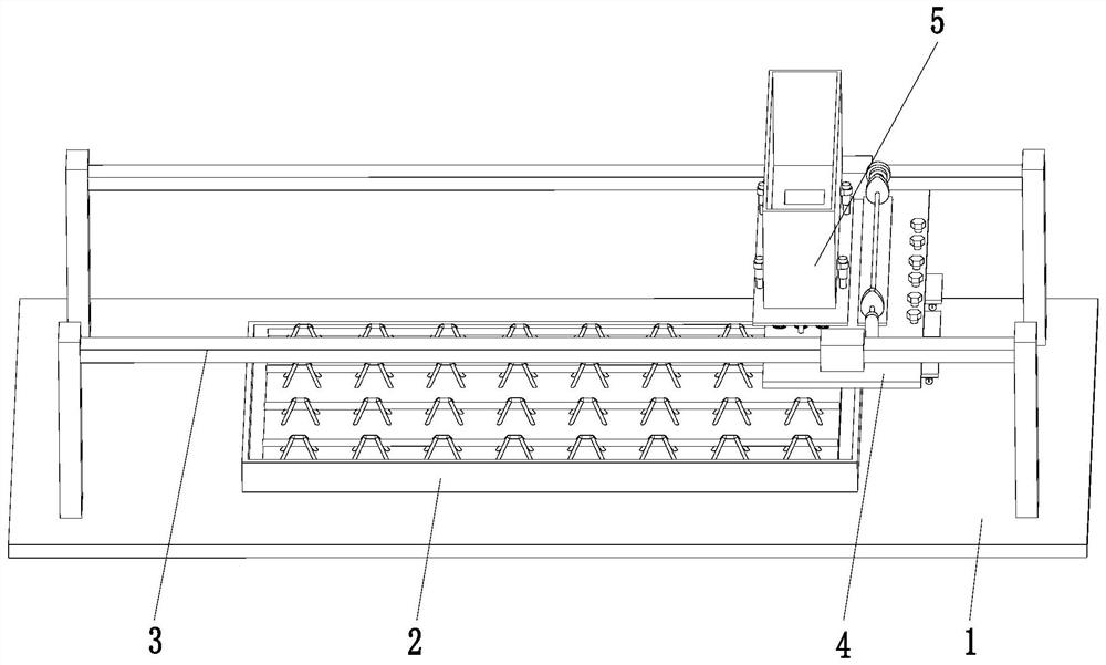
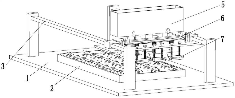
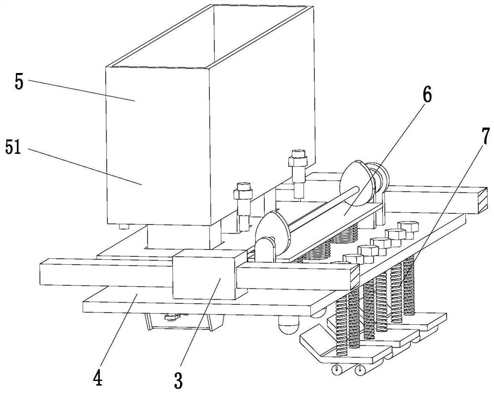
[0030] Such as Figure 1 to Figure 8 As shown, a prefabricated laminated floor preparation process for a prefabricated building, the floor preparation process uses the following prefabricated laminated floor preparation device, the prefabricated laminated floor preparation device includes a base plate 1, a floor formwork 2, an electric slider group 3, Workbench 4, blanking device 5, vibration mechanism 6 and smoothing mechanism 7, the floor formwork 2 is installed on the top middle of the bottom plate 1, and the electric slider group 3 is symmetrically arranged on the front and rear ...


PUM


Abstract

The invention relates to a manufacturing process of a prefabricated building precast composite floor slab. A floor slab manufacturing process adopts the following precast composite floor slab manufacturing device, and the precast composite floor slab manufacturing device comprises a bottom plate, a floor slab mold frame, an electric sliding block group, a workbench, a discharging device, a vibrating mechanism and a smoothing mechanism. The discharging device comprises a cement tank, an opening push rod, a discharging pipeline and an opening mechanism. The floor slab manufacturing process adopting the precast composite floor slab manufacturing device comprises the following steps that S1, a framework is placed; S2, cement blanking is performed; S3, the cement is oscillated; and S4, a surface is smoothed. Problems that an existing precast composite floor slab production machine is uneven in concrete paving and scattering in a concrete pouring process so that a defective rate of producedprecast floor slabs is high, and strength of the precast floor slabs is affected due to a fact that an existing precast floor slab production machine is poor in vibrating effect in a vibrating and guiding process can be solved.

Description

technical field [0001] The invention relates to the technical field of prefabricated buildings, in particular to a preparation process for prefabricated laminated floor slabs of prefabricated buildings. Background technique [0002] The prefabricated laminated slab is produced by the factory, transported to the site for installation, and used as an assembled monolithic slab formed by laminating the lower part of the slab and the cast-in-place reinforced concrete surface. The prefabricated laminated floor itself can be used as a mold for the cast-in-place reinforced concrete layer, which saves formwork, and the bottom surface of the thin slab is flat and smooth, and the ceiling of the building does not need to be plastered, which reduces indoor wet work and speeds up the construction progress. Widely used in construction. At present, the production method of domestic prefabricated laminated slabs is generally to install the mold first, then install the steel skeleton, and th...

Claims


Application Information

Patent Timeline
Patent Type & Authority Patents(China)
IPC IPC(8): B28B1/093B28B1/29B28B23/02E04B5/17
CPCB28B1/093B28B1/0935B28B1/29B28B23/02E04B5/17
Inventor 王国超
Owner 山东鸿琨住工科技有限公司
Why Eureka
Try Eureka