
On-orbit inspection linear motion mechanism and on-orbit inspection device

A technology of linear motion and driving mechanism, applied in transportation and packaging, measuring devices, motor vehicles, etc., can solve the problems of reduced sealing performance, structural deformation, temperature rise, etc., and achieve the effect of ensuring sustainable driving

Active Publication Date: 2020-04-21
TECH & ENG CENT FOR SPACE UTILIZATION CHINESE ACAD OF SCI
View PDF6 Cites 2 Cited by
  • Summary
  • Abstract
  • Description
  • Claims
  • Application Information

AI Technical Summary

Problems solved by technology

[0008] (2) Effect of pressure difference
[0009] The effect of differential pressure is usually in the range of 1×10- 2 Pa~1×10- 5 Occurs in the vacuum range of Pa. When there is a sealed structure in the spacecraft, the internal and external differences of the sealed structure will increase, resulting in structural deformation or damage
[0010] (3) Effect of vacuum outlet
Released gases can re-condense on colder components, contaminating optics, sensors, and thermal control coatings with optically selective properties, resulting in reduced optical performance, increased solar absorption, and elevated temperatures
[0012] (4) Effect of radiation heat transfer
[0017] (6) Micro meteors and space debris
Once these institutions leak, the consequences will be quite serious
The complexity of the space environment will lead to the aging of the sealing material and the reduction of the sealing performance. Therefore, the sealing design is also an important part of the reliability design of the spacecraft.

Method used


Image

  • On-orbit inspection linear motion mechanism and on-orbit inspection device
  • On-orbit inspection linear motion mechanism and on-orbit inspection device
  • On-orbit inspection linear motion mechanism and on-orbit inspection device

Examples


Embodiment 1

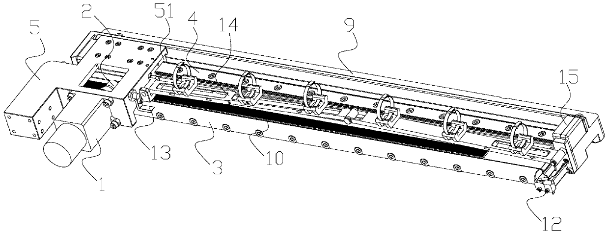
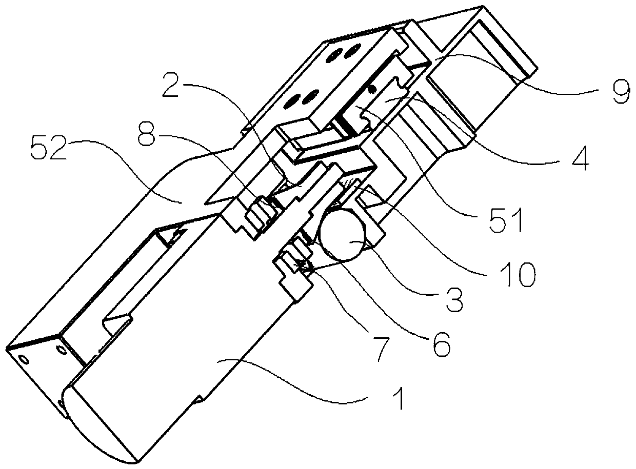
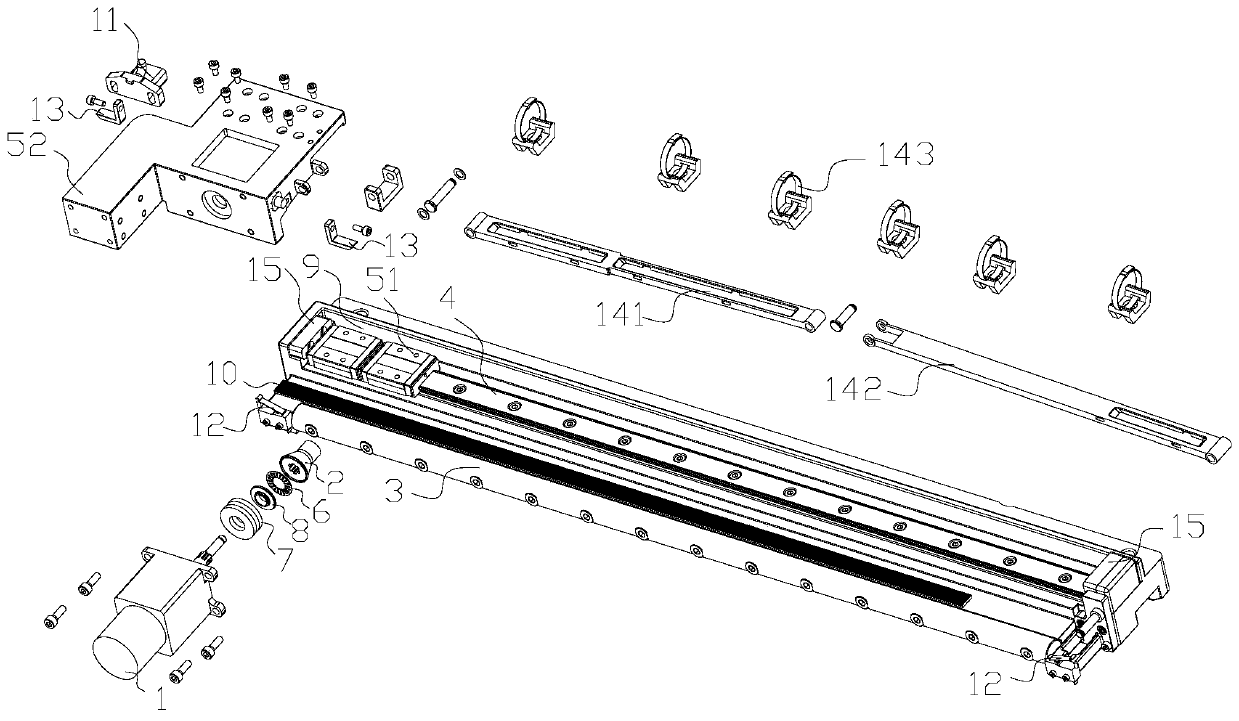
[0080] Such as Figure 1-6 As shown, an on-orbit inspection linear motion mechanism includes:

[0081] drive mechanism 1,

[0082] The conical friction wheel 2 is splined to the output shaft of the drive mechanism 1, and the spline section of the conical friction wheel 2 is larger than the spline section of the output shaft of the drive mechanism 1;

[0083] The friction rod 3 is frictionally matched with the conical friction wheel 2; the conical outer peripheral side of the conical friction wheel 2 abuts on the friction rod 3;

[0084] The guide rail 4 is arranged in parallel with the friction bar 3;

[0085] A slider assembly 5, one end of the slider assembly 5 is slidably mounted on the guide rail 4, and the other end is fixedly connected with the casing of the drive mechanism 1;

[0086] The spring 6 is sheathed on the output shaft of the driving mechanism 1, and sandwiched between the big end of the conical friction wheel 2 and the other end of the slider assembly 5; t...

Embodiment 2

[0118] An on-orbit inspection device for material exposure optical space, including an inspection mechanism and an on-orbit inspection linear motion mechanism as described above, the on-rail inspection linear motion mechanism and the inspection mechanism are parallel to the exposed surface of the material to be inspected , the inspection mechanism is fixedly connected with the slider assembly 5 , an optical imaging module is slidably installed on the inspection mechanism, and the sliding direction of the optical imaging module is perpendicular to the guide rail 4 .

[0119] Specifically, in some embodiments, the inspection mechanism has the same structure as the above-mentioned on-rail inspection linear motion mechanism. The slider plate 52 is fixedly connected, and an optical imaging module is fixedly installed on the slider plate 52 of the inspection mechanism. The optical imaging system moves horizontally and linearly, and the optical imaging module slides on the inspection...


PUM


Abstract

The invention relates to an on-orbit inspection linear motion mechanism and an on-orbit inspection device, and the on-orbit inspection linear motion mechanism comprises a drive mechanism, a conical friction wheel, a friction rod, a guide rail, a sliding block assembly, and a spring. The conical friction wheel is connected with the drive mechanism. The friction rod is in friction fit with the conical friction wheel, and the peripheral side of the conical friction wheel abuts against the friction rod. The guide rail is parallel to the friction rod; one end of the sliding block assembly is slidably mounted on the guide rail, and the other end of the sliding block assembly is fixedly connected with the drive mechanism; the spring sleeves the output shaft of the drive mechanism and is clamped between the conical friction wheel and the sliding block assembly; and the spring is in compressed state. Guiding and limiting are provided through the guide rail. Under the action of high temperatureand low temperature outside the cabin, various materials have different deformations, so that failure modes such as disappearance of pressure between the conical friction wheel and the friction rod orblockage of the guide rail and the sliding block are possibly caused; and certain spring force is used for pre-tightening, so that enough temperature difference adjusting space exists in the device,the on-orbit inspection linear motion mechanism and the on-orbit inspection device can adapt to high and low temperature changes outside a cabin, and high environmental adaptability and reliability are achieved.

Description

technical field [0001] The invention relates to the field of space linear motion mechanisms, in particular to an on-rail inspection linear motion mechanism and an on-rail inspection device. Background technique [0002] In space science research, it is inseparable from the use of various materials, especially new materials. The purpose of material space environment exposure experiment is to study the service behavior of materials under the effect of special space environment. [0003] 1. Influence of space environment on mechanism reliability [0004] Compared with the institutions working on the ground, the working difference of space institutions is mainly caused by the space environment, and the space dynamic environment is different from the ground environment. [0005] 1.1 Influence of space environment [0006] (1) Microgravity influence [0007] Since the current spacecraft is usually adjusted on the ground, that is, under the action of gravity, when the spacecraf...

Claims


Application Information

Patent Timeline
Patent Type & Authority Applications(China)
IPC IPC(8): B64G1/10B64G1/66G01N17/00
CPCB64G1/105B64G1/66G01N17/00G01N17/004G01N17/006
Inventor 张聚乐张伟贵王乐天王珂王辅辅乔志宏冯振华
Owner TECH & ENG CENT FOR SPACE UTILIZATION CHINESE ACAD OF SCI
Learn More