Two-stage low-temperature gasification device and method based on low-order fuel autocatalysis
A low-temperature gasification and fuel technology, applied in the direction of granular/powdered fuel gasification, gasification process, and production of combustible gas, can solve the problems of increased tar content, reduced catalyst content, unfavorable tar retention, etc.
- Summary
- Abstract
- Description
- Claims
- Application Information
AI Technical Summary
Problems solved by technology
Method used
Image
Examples
specific Embodiment approach 1
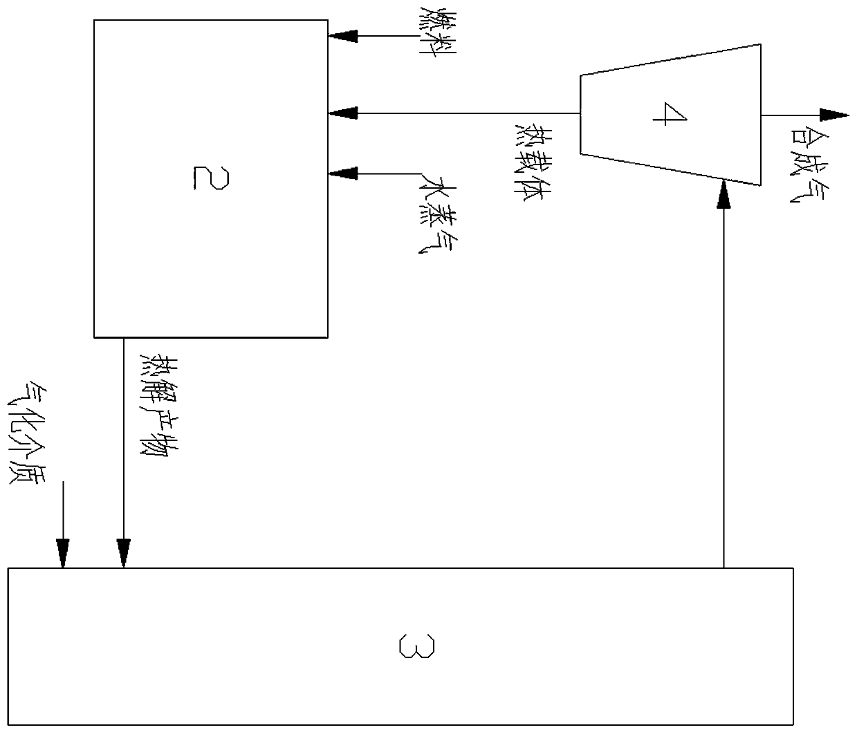
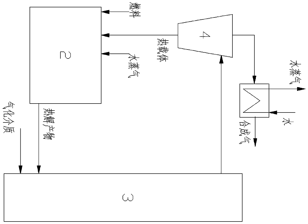
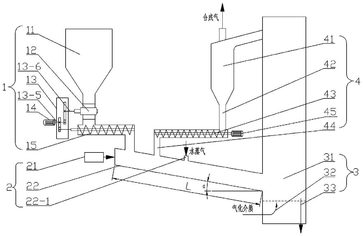
[0033] Specific implementation mode one: as figure 1 , image 3 , Figure 5 As shown, this embodiment discloses a two-stage low-temperature gasification device based on low-order fuel autocatalysis, which consists of a feeding system 1, a moving bed pyrolysis system 2, a fluidized bed gasification system 3 and cyclone separation System 4;
[0034] The feeding system 1 includes a feed bin 11, an air lock 12, a gear box 13, a motor one 14 and a screw feeder 15, and the moving bed pyrolysis system 2 includes an electric vibrator 21 and a pyrolysis reaction 22, the fluidized bed gasification system 3 includes a fluidized bed gasifier 31, an air inlet system 32 and a slag discharge pipe 33, and the cyclone separation system 4 includes a spiral feeder 43, a secondary feeder Pipe 44, at least one cyclone separator 41 and at least one primary return pipe 42;
[0035] The air shutoff device 12 is arranged at the lower part of the silo 11, the power output shaft of the motor one 14 ...
specific Embodiment approach 2
[0042] Specific implementation mode two: as image 3 , Figure 4 As shown, this embodiment is a further limitation of Embodiment 1, the angle between the bottom surface of the pyrolysis reactor 22 and the horizontal plane is α, α=20°~45°. For low-order fuels with different particle mobility, continuous and stable fuel feeding is ensured under low energy consumption of the electrodynamic vibrator 21 .
specific Embodiment approach 3
[0043] Specific implementation mode three: as image 3 , Figure 4 As shown, the present embodiment is a further description of specific embodiment one, assuming that the length of the pyrolysis reactor 22 is L, and the initial position of the length of the pyrolysis reactor 22 is located at the fuel inlet of the pyrolysis reactor 22 At one end, the steam inlet 22-1 is set in the 1 / 3L~1 / 2L area of the pyrolysis reactor 22 in the length direction (for supplementing the moisture required for the gasification and reforming of the pyrolysis product).
[0044] Specific implementation mode four: as image 3 , Figure 4 As shown, this embodiment is a further description of the third specific embodiment. The secondary return pipe 44 is located in the 1 / 3L area of the pyrolysis reactor 22 in the length direction (to ensure that the heat carrier and the low-order sufficient fuel contact and heat transfer).
PUM
| Property | Measurement | Unit |
|---|---|---|
| particle diameter | aaaaa | aaaaa |
Abstract
Description
Claims
Application Information
 - R&D
- Intellectual Property
- Life Sciences
- Materials
- Tech Scout
- Unparalleled Data Quality
- Higher Quality Content
- 60% Fewer Hallucinations
Browse by: Latest US Patents, China's latest patents, Technical Efficacy Thesaurus, Application Domain, Technology Topic, Popular Technical Reports.
© 2025 PatSnap. All rights reserved.Legal|Privacy policy|Modern Slavery Act Transparency Statement|Sitemap|About US| Contact US: help@patsnap.com


