A spill-proof cement floor calender
A technology of calendering machine and ground, which is applied in the direction of construction and building construction, can solve the problems of reducing the quality of cement calendering processing, uneven ground, and insufficient technical considerations, and achieve the effect of improving smoothness and processing quality
- Summary
- Abstract
- Description
- Claims
- Application Information
AI Technical Summary
Problems solved by technology
Method used
Image
Examples
Embodiment 1
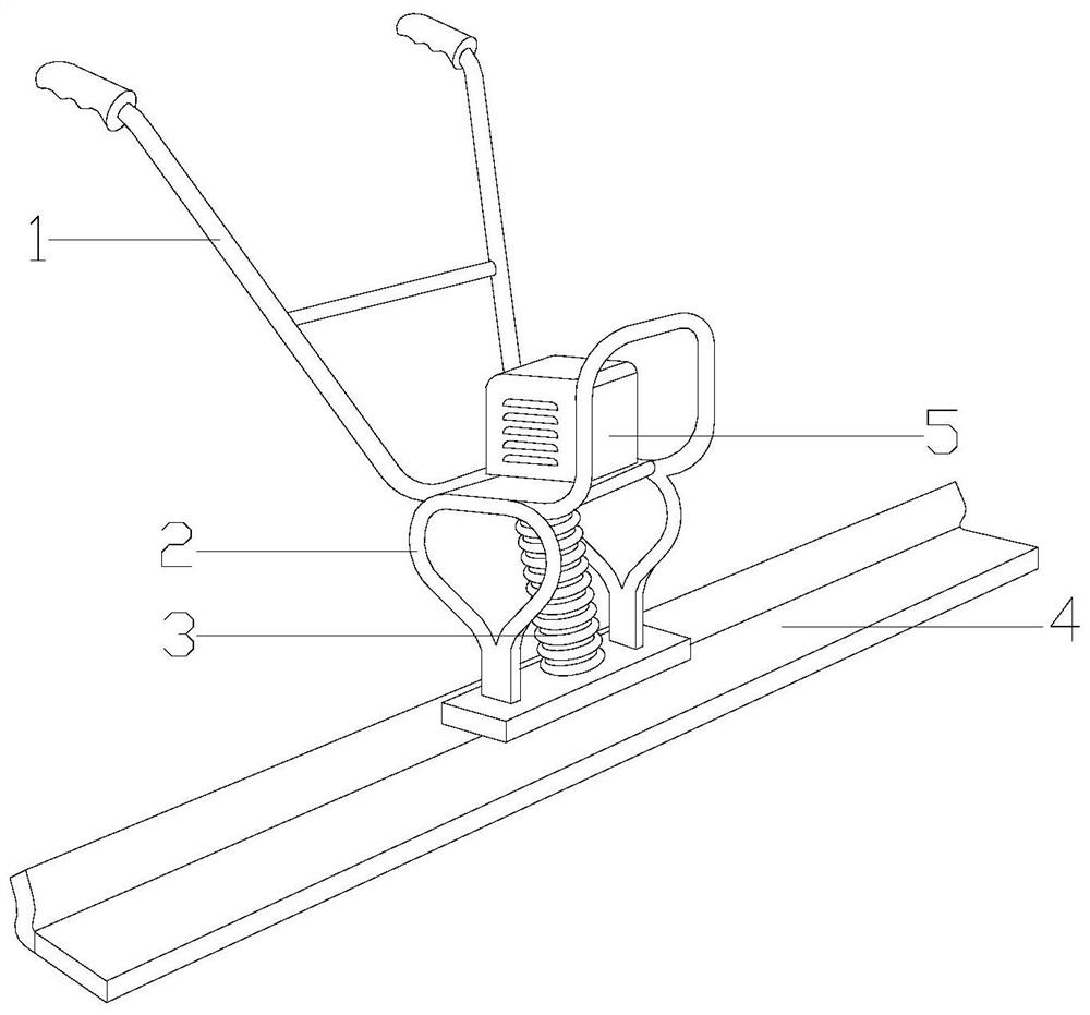
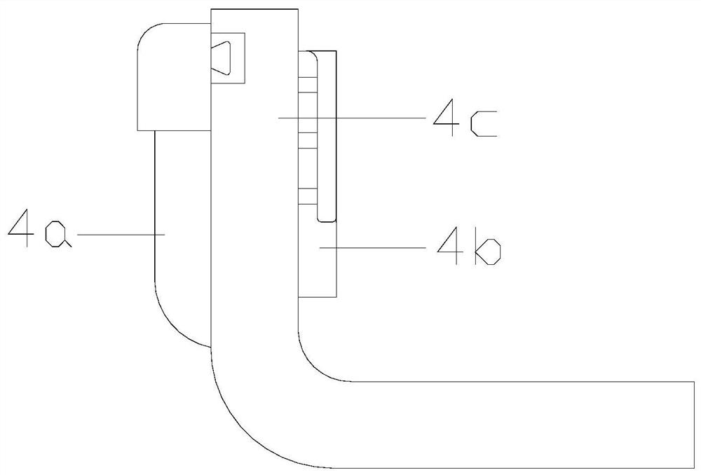
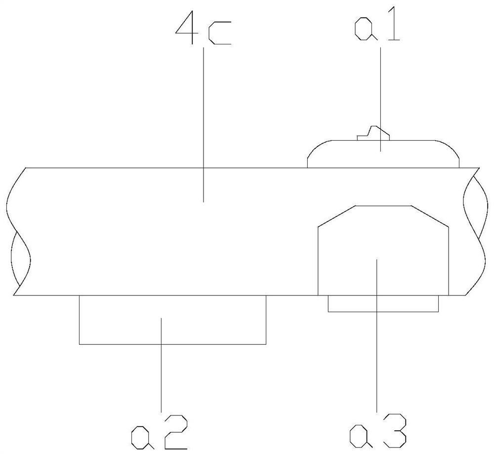
[0031] see Figure 1-Figure 6, the present invention provides an anti-spill cement floor calender, the structure of which includes a non-slip operating handle 1, a side beam connecting frame 2, a closed damping shaft 3, a ground calendering structure 4, and an electric motor 5, the ground calendering The structure 4 has an L-shaped structure and is bonded to the cement floor. The side beam connecting frame 2 and the ground calendering structure 4 are fixed together by bolts. The electric motor 5 is installed on the upper surface of the side beam connecting frame 2. The closed damping shaft 3 is located in the middle of the side beam connecting frame 2 and fastened with the ground calendering structure 4, the anti-slip operating handle 1 and the side beam connecting frame 2 are fixed together by bolts, and the ground calendering structure 4 is fixed by sliding The anti-overflow leveling device 4a, connecting pinch plate 4b, vibrating ruler main body 4c, and swing anti-overflow ...
Embodiment 2
[0034] see Figure 7-Figure 11 , the swing anti-overflow leveling device 4d is composed of a swing smoothing device d1, an installation groove d2, and a rotating push structure d3. On the left side of the groove d2, the rotation pushing structure d3 is interlocked with the swing smoothing device d1, and the swing smoothing device d1 is parallel to the vibrating ruler main body 4c. The swing smoothing device d1 is composed of a rotating vibration structure d11, a mud pusher d12, a cement smoothing plate d13, a traction shaft frame d14, and a protective shell d15. The protective shell d15 is nested in the installation groove d2, and the traction shaft The frame d14 is vertically installed in the middle of the protective shell d15, the cement smoothing plate d13 is fastened with the traction shaft frame d14, the rotating vibration structure d11 is located on the top of the traction shaft frame d14, and the mud pushing plate d12 passes through the main body 4c of the vibrating rul...
PUM
 Abstract
Description
Claims
Application Information
 - R&D
- Intellectual Property
- Life Sciences
- Materials
- Tech Scout
- Unparalleled Data Quality
- Higher Quality Content
- 60% Fewer Hallucinations
Browse by: Latest US Patents, China's latest patents, Technical Efficacy Thesaurus, Application Domain, Technology Topic, Popular Technical Reports.
© 2025 PatSnap. All rights reserved.Legal|Privacy policy|Modern Slavery Act Transparency Statement|Sitemap|About US| Contact US: help@patsnap.com


