Rotary cut-expanded branch pile machine and construction method of cut-expanded branch pile

A construction method and technology of supporting disk piles, which are applied in sheet pile walls, earthwork drilling, infrastructure engineering, etc., can solve the problems of long construction time, low construction efficiency, small lateral area increment, etc., saving construction time, The effect of speeding up construction progress and reducing the number of installations

CN111042738APending Publication Date: 2020-04-21CHANGAN UNIV
0 Cites 7 Cited by

Patent Information

Authority / Receiving Office
CN · China
Patent Type
Applications(China)
Current Assignee / Owner
Publication Date
2020-04-21

Smart Images

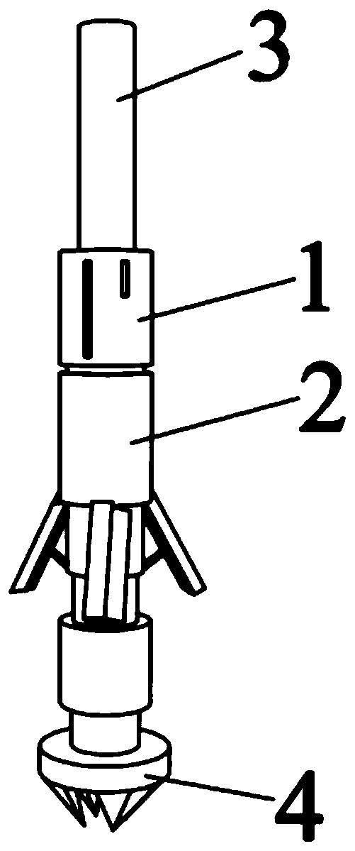
  • Figure 1
    Figure 1
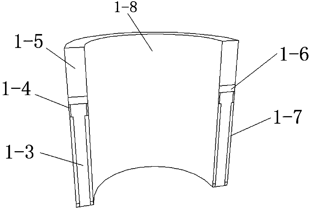
  • Figure 2
    Figure 2
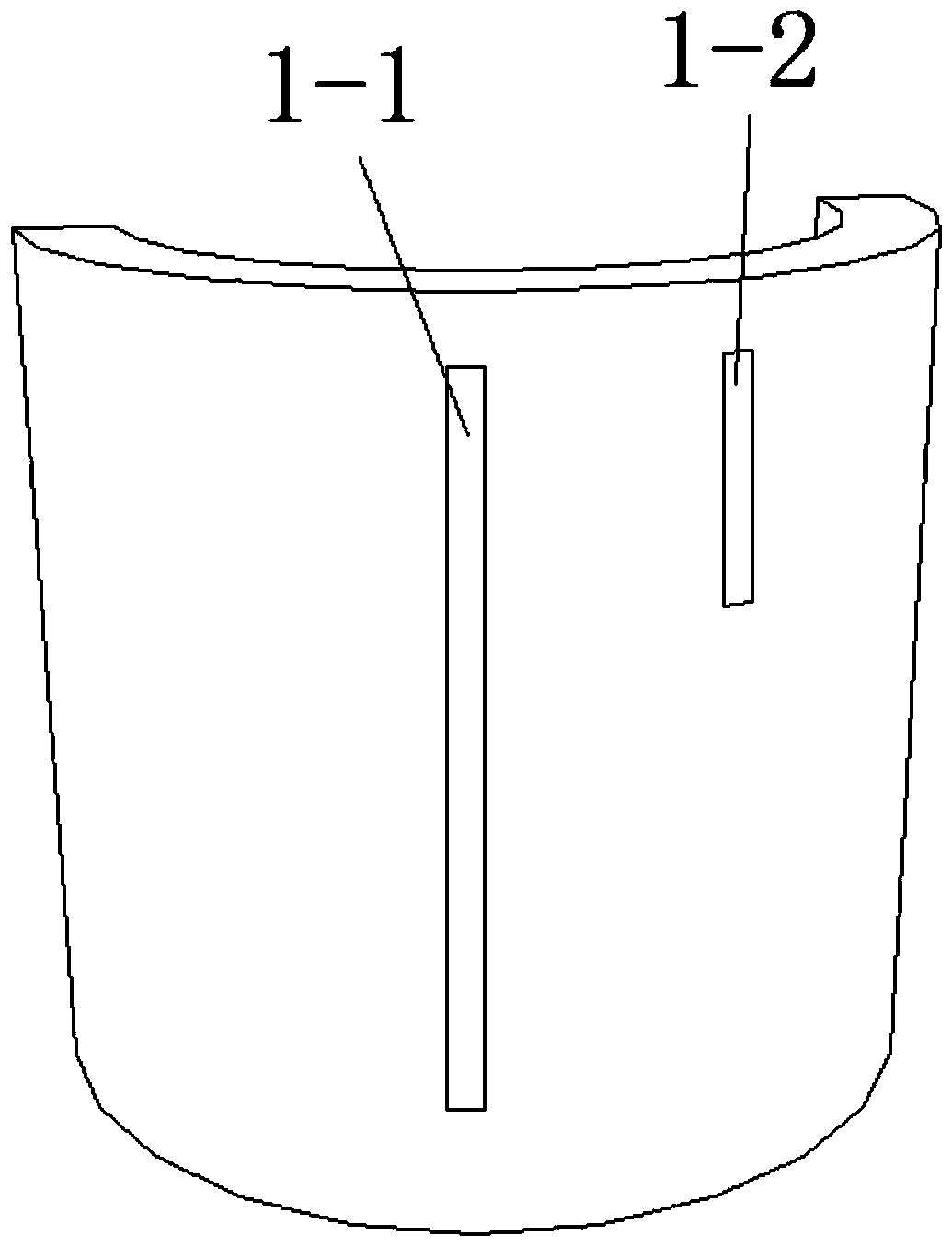
  • Figure 3
    Figure 3
Patent Text Reader

Abstract

The invention discloses a rotary cut-expanded branch pile machine and a construction method of a cut-expanded branch pile. The cut-expanded branch pile comprises a drill rod, and a rotary cut-expanding assembly is fixed to the drill rod. The rotary cut-expanding assembly comprises a first force transferring barrel, and a plurality of soil cutting steel plates are hinged to the lower end of the first force transferring barrel. First sliding grooves are formed in the inner walls of the soil cutting steel plates. The lower end of a second force transferring barrel stretches inwards to form a pressing block, and a buckle seat is fixed to a connecting barrel. A spring is mounted on the side wall of the buckle seat, the lower end of the spring and the lower end of a mounting groove are fixed, and the upper end of the spring seat and a buckle are fixedly connected. One end of each connecting rod is fixed into the corresponding first sliding groove, and the other ends of the connecting rods are mounted on the buckle. When the drill bit reaches a target position, the soil cutting steel plates work under the action of a hydraulic component, the rotary speed and angles of the soil cutting steel plates achieve stepless speed change, and finally a tree-shaped branch plate cavity is formed in the same position. Compared with a common branch pile, the formed tree-shaped branch pile has the advantages that the size is larger, and the vertical and transverse axial bearing capacity of a pile foundation is remarkably improved.
Need to check novelty before this filing date? Find Prior Art

Description

technical field

[0001] The invention belongs to the technical field of forming poured branch piles, and in particular relates to a rotary cutting and expanding branch pile machine and a construction method of cutting and expanding branch piles. Background technique

[0002] Support disc pile is a new type of pile foundation technology. By squeezing and expanding in a suitable soil layer, a cast-in-place pile with a support disc is formed, which greatly improves the bearing capacity of a single pile, reduces the pile diameter and pile length, saves costs, and shortens the construction period. , has been widely used in many cities.

[0003] Disc piles are ordinary friction piles or friction end-bearing piles in relatively weak soil layers, which can increase the bearing capacity of pile ends by setting bearing plates or bearing branches within a limited range of pile body soil layers, and make full use of all areas within the pile body. The bearing capacity of the pile end of...

Examples

Embodiment Construction

[0043] In order to make the purpose and technical solution of the present invention clearer and easier to understand. The present invention will be further described in detail below in conjunction with the drawings and embodiments. The specific embodiments described here are only used to explain the present invention, not to limit the present invention.

[0044]In describing the present invention, it should be understood that the terms "center", "longitudinal", "transverse", "upper", "lower", "front", "rear", "left", "right", " The orientations or positional relationships indicated by "vertical", "horizontal", "top", "bottom", "inner" and "outer" are based on the orientations or positional relationships shown in the drawings, and are only for the convenience of describing the present invention and Simplified descriptions, rather than indicating or implying that the device or element referred to must have a particular orientation, be constructed and operate in a particular orie...