Rotor system and micro gas turbine generator unit

A rotor and compressor technology, applied in gas turbine installations, machines/engines, mechanical equipment, etc., can solve the problems of rotor system gravity center deviation, poor rotor system stability, coupling damage, etc., to achieve small mechanical friction loss and reduce processing. Accuracy and assembly accuracy, effect of short axial dimension

Pending Publication Date: 2020-04-21
TECH XANADU OF RESONATORY SOLAR SYSTD CO LTD +1
View PDF0 Cites 1 Cited by
  • Summary
  • Abstract
  • Description
  • Claims
  • Application Information

AI Technical Summary

Problems solved by technology

The setting of the coupling restricts the setting position of the thrust bearing, because as the rotor speed increases, the axial force on the rotor will further increase. If the thrust bearing is set between the compressor and the turbine, it will make the The center of gravity of the entire rotor system is biased toward the turbine side, resulting in poor stability of the rotor system
If the thrust bearing is placed on the side of the coupling facing the generator, all the axial force of the rotor will act on the coupling, which will easily cause damage to the coupling

Method used


Image

  • Rotor system and micro gas turbine generator unit
  • Rotor system and micro gas turbine generator unit
  • Rotor system and micro gas turbine generator unit

Examples


Embodiment Construction

[0045] In order to better understand the technical solutions of the present invention, the present invention will be further described below in conjunction with specific embodiments and accompanying drawings.

[0046] According to one aspect of the invention, a rotor system is provided.

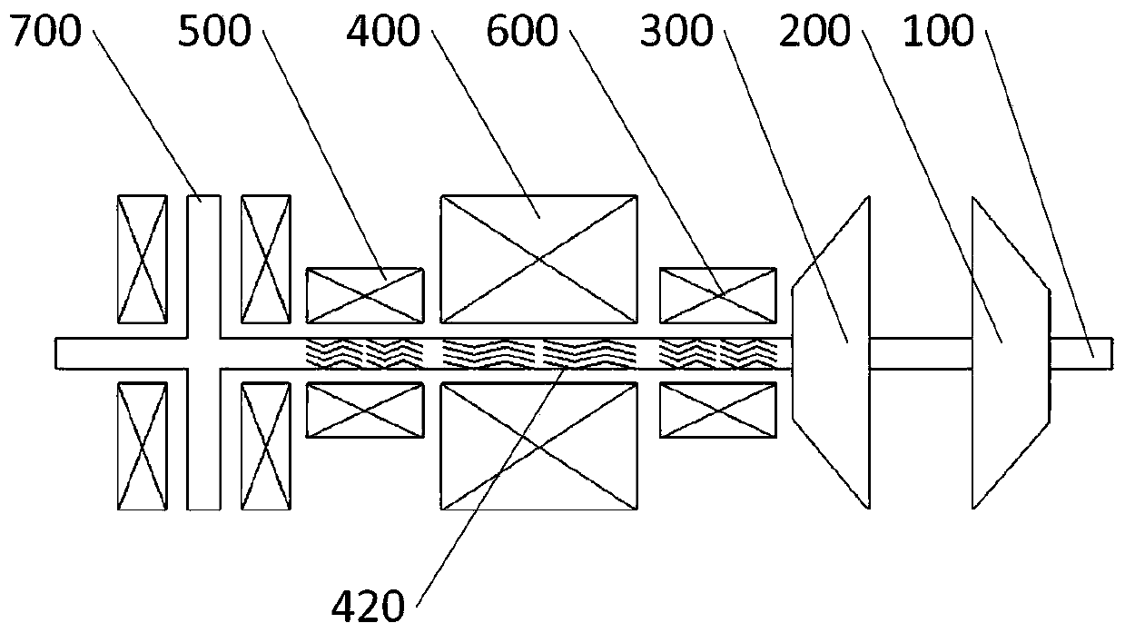
[0047] Such as figure 1 As shown, the rotating shaft 100, the turbine 200, the compressor 300, the motor 400, the first radial bearing 500, the second radial shaft 600 and the thrust bearing 700, the rotating shaft 100 passes through the thrust bearing 700, The first radial bearing 500, the motor 400, the second radial bearing 600, the compressor 300, and the turbine 200, the rotating shaft 100 is on the stator of the thrust bearing 700, the first radial bearing 500, and the The stator and the second radial bearing 600 rotate inside, and the rotating shaft 100 is fixedly connected with the thrust plate of the thrust bearing 700 , the turbine wheel of the turbine 200 , and the compression whe...


PUM


Abstract

The invention provides a rotor system and a micro gas turbine generator unit. The rotor system comprises a rotating shaft, a thrust bearing, a first radial bearing, a motor, a second radial bearing, agas compressor and a turbine, wherein the rotating shaft is of an integrally-formed structure, and the thrust bearing, the first radial bearing, the motor, the second radial bearing, the gas compressor and the turbine are sequentially arranged on the rotating shaft. The rotating shaft rotates in a stator of the thrust bearing, the first radial bearing, a motor stator and the second radial bearing, and the rotating shaft is fixedly connected with a thrust disc of the thrust bearing, a worm wheel of the turbine and a compression wheel of the gas compressor. The integral rotating shaft is adopted for connecting a micro gas turbine rotor and a generator rotor, the thrust bearing is arranged at the end with a generator, and the technical problem that the arrangement position of the thrust bearing is limited in the prior art is solved.

Description

technical field [0001] The invention relates to the technical field of rotor dynamics, in particular to a rotor system and a micro gas turbine generating set. Background technique [0002] The micro gas turbine is a newly developed small heat engine, its stand-alone power ranges from 25 to 300kW, and its basic technical features are radial flow impeller machinery and regenerative cycle. A micro gas turbine mainly includes three major components: a compressor, a combustor and a turbine. After the air enters the compressor, it is compressed into high-temperature and high-pressure air, and then supplied to the combustion chamber for mixed combustion with fuel, and the high-temperature and high-pressure gas generated expands in the turbine to perform work. When the rotor rotates at high speed, the rotor will be subjected to radial force and axial force. In order to limit the radial and axial movement of the rotating shaft, radial bearings and thrust bearings need to be install...

Claims


Application Information

Patent Timeline
Patent Type & Authority Applications(China)
IPC IPC(8): F02C7/12F02C7/18F02C7/06F02C7/20F02C7/32F02C6/00F02C3/04
CPCF02C3/04F02C6/00F02C7/06F02C7/12F02C7/18F02C7/20F02C7/32
Inventor 靳普刘慕华
Owner TECH XANADU OF RESONATORY SOLAR SYSTD CO LTD
Why Eureka
Try Eureka