Hydrodynamic retarder with front stator

A retarder and pre-hydraulic technology, applied in the direction of hydraulic resistance brakes, couplings, clutches, etc., can solve the problems of small retarder torque, no-load loss, and difficult spatial arrangement of hydraulic retarders, etc. The effect of increasing retarder torque, reducing weight, improving strength and reliability

Pending Publication Date: 2020-04-21
FAWER AUTOMOTIVE PARTS
View PDF0 Cites 10 Cited by
  • Summary
  • Abstract
  • Description
  • Claims
  • Application Information

AI Technical Summary

Problems solved by technology

[0008] The invention discloses a hydraulic retarder at the front of the stator to solve the no-load loss caused by the low torque of the retarder in the prior art and the anti-torsion connection between the retarder input gear and the retarder shaft. Issues such as difficulty in spatial layout of rear-mounted hydraulic retarder in parallel connection of gearboxes

Method used


Image

  • Hydrodynamic retarder with front stator
  • Hydrodynamic retarder with front stator
  • Hydrodynamic retarder with front stator

Examples


Embodiment Construction

[0024] An embodiment of the present invention will be described in detail below in conjunction with the accompanying drawings.

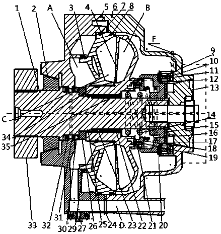
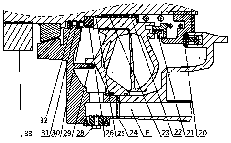
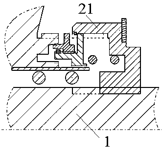
[0025] Examples of the present invention figure 1 , figure 2 , image 3 As shown, it includes retarder shaft 1, front bearing 2, stator 3, rotor 4, stator end cover 5, body 6, stator sealing ring 7, rotor sealing ring 8, annular piston oil seal 9, annular meshing piston 10, Ring type end face bearing 11, ring type piston double seal 12, rear bearing 13, release spring 14, active meshing gear end face bearing 15, locking sliding frame return spring 16, meshing gear 17, locking sliding frame 18, synchronous lock Stop ring snap ring 19, end face bearing 20, synchronous lock ring 21, rotor needle roller bearing 22, rotor needle roller bearing positioning ring 23, oil return passage seal 24, rotor sealing ring 25, rotor positioning ring and end face bearing 26, Output temperature sensor 27, working chamber input oil temperature sensor 28, stator input...


PUM


Abstract

The invention discloses a hydrodynamic retarder with a front stator. The retarder comprises a retarder shaft, a front bearing, a stator, a rotor, a stator end cover, a body, a separation spring, an annular piston, a meshing gear, a locking sliding framework, a return spring, a synchronous locking ring, a needle roller bearing, an outer oil seal and the like, wherein a high-pressure oil outlet cavity B is closed by the stator and the stator end cover, a low-pressure oil inlet cavity A is formed by closing the retarder shaft; the stator is arranged in front of the rotor, the rotor is arranged behind the stator, and the stator and the rotor are arranged in a closed cavity in the body; a sealing ring is arranged between the rotor and the stator and is used for isolating a working cavity C fromthe oil inlet cavity A; when no load exists, a meshing gear is pushed by a separation spring to move rightwards to a right positioning dead point, the meshing gear is separated from the rotor, the rotor does not rotate with the shaft any more, and thereby no-load loss can be caused even though a small amount of media exist in the working cavity C; an oil duct is arranged in front of the stator, the radial size is reduced, and interference with a transmission shaft is avoided. The retarder is advantaged in that the weight is reduced to the maximum extent, noise is reduced, strength and reliability are improved, and no-load loss is reduced.

Description

technical field [0001] The invention belongs to the technical field of automobile engineering, and relates to a hydraulic retarder at the front of the stator, in particular to a hydraulic retarder at the front of the stator and an integral separable rotor at the rear; The input gear of the speed reducer is connected with the retarder shaft in a torsion-proof manner. Background technique [0002] A hydraulic retarder is a retarder that reduces the speed of a vehicle through a hydraulic device. The hydraulic retarder is also called a hydraulic retarder. [0003] If the speed of the car is too fast when turning or going downhill, it is easy to cause traffic accidents, and frequent use of the driving brake for a long time will not only cause serious wear and tear, but more importantly, the brakes will overheat, and even the brakes will fail due to serious thermal degradation of the brakes. The serious consequences of fire, so non-contact, active heat dissipation devices such as...

Claims


Application Information

Patent Timeline
Patent Type & Authority Applications(China)
IPC IPC(8): F16D67/02F16D57/00F16D65/78F16H57/04
CPCF16D57/00F16D65/0006F16D65/78F16D67/02F16D2300/0214F16H57/0413F16H57/042F16H57/045F16H57/0457F16H57/0471F16H57/0472
Inventor 任孝义王文辉沈栋平陈利高凤才马琳张昊琦王彤
Owner FAWER AUTOMOTIVE PARTS
Why Eureka
Try Eureka