
Power tube well cable information acquisition and storage device and method

A technology of information collection and storage devices, which is applied in the direction of measuring devices, cooperative operation devices, signal transmission systems, etc., can solve the problems of short communication distance, small coverage, difficult maintenance and replacement, etc., to improve survivability or lifespan, guarantee Stability and reliability, the effect of improving work flexibility

Active Publication Date: 2020-04-21
康威通信技术股份有限公司
View PDF15 Cites 2 Cited by
  • Summary
  • Abstract
  • Description
  • Claims
  • Application Information

AI Technical Summary

Problems solved by technology

[0003] The stock of cable pipe drainage is huge. Due to its own structural characteristics, joint wells and cross wells are independent and scattered. It is very difficult to count and manage line equipment and related resources, difficult to repair and replace, and it is impossible to implement unified monitoring.
[0004] The inventors of the present disclosure found that (1) the current outer cover monitoring products on the market can only realize the management of the entrance of the joint well, and lack effective management and monitoring means for important equipment such as lines and joints in the well, such as accurate information and positioning statistics of lines , The running status of the joints is a difficult point in maintenance and management in production; (2) There are few products on the market for information collection of power pipe well cables, and the wireless working frequency band of their products is mostly at the GHz level, the communication distance is short, and the coverage Small, and application scenarios generally do not consider low power consumption requirements

Method used


Image

  • Power tube well cable information acquisition and storage device and method

Examples


Embodiment 1

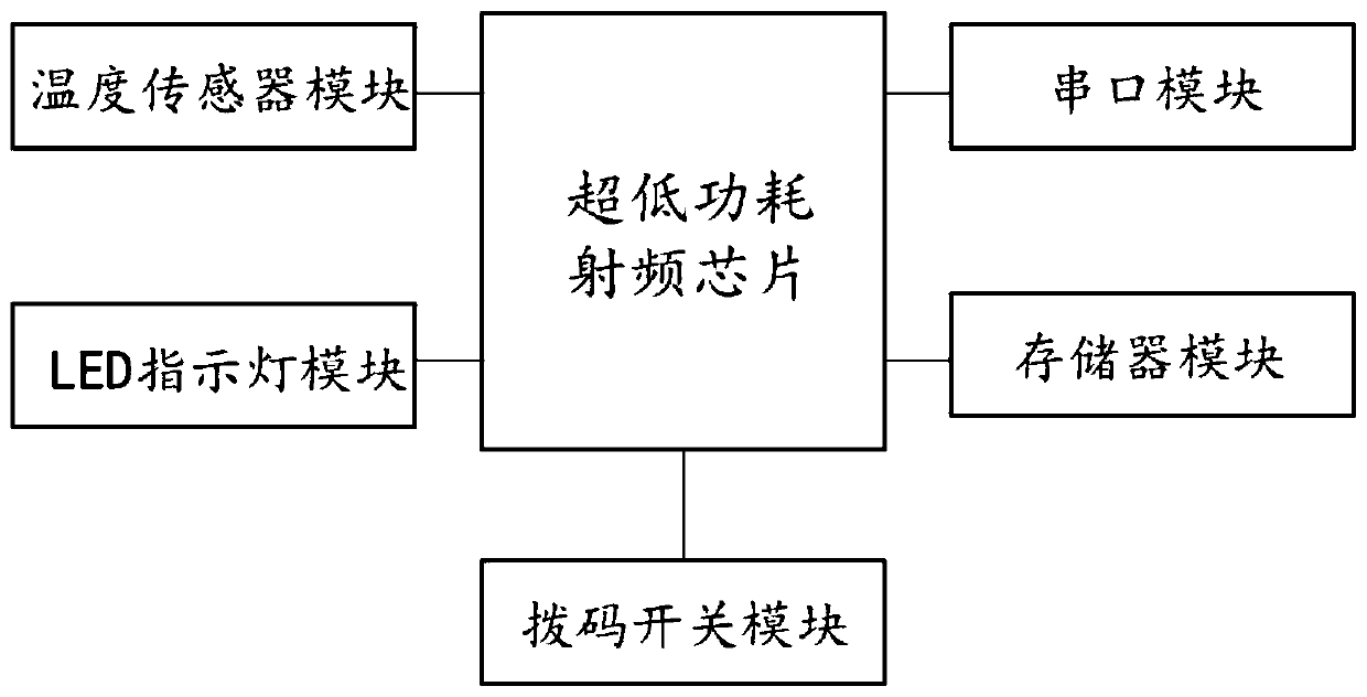
[0044] Such as figure 1 As shown, Embodiment 1 of the present disclosure provides an information collection and storage device for power pipe well cables, including an electronic tag body, and the electronic tag body includes a control module, an indicator light module, a temperature sensor module, and a storage module. The control module respectively connected with the indicator light module, the temperature sensor module and the storage module;

[0045] The control module is an ultra-low-power radio frequency chip, which is used for two-way communication with an external concentrator to realize data transmission and reception. The MCU is an ultra-low-power radio frequency chip of TI company below 1GHz, and its main function is to run The TI-RTOS operating system correctly configures the working parameters of the peripherals, drives the radio frequency core to realize the transmission and reception of wireless data, and has a coprocessor specially for sensor control, which ef...


PUM


Abstract

The disclosure provides a power tube well cable information acquisition and storage device and method. The device comprises an electronic tag body. The electronic tag body comprises a control module,an indication lamp module, a temperature sensor module and a storage module. The control module is connected with the indication lamp module, the temperature sensor module and the storage module; thecontrol module is an ultra-low power consumption radio frequency chip and is used for carrying out bidirectional communication with an external concentrator to realize data transceiving, the indication lamp module is used for indicating whether data transceived by the electronic tag are normal or not; the temperature sensor module is used for detecting the temperature of an environment where the cable is located; and the storage module is used for storing static information of the cable. The electronic tag body is arranged in a closed plastic shell, and the plastic shell is fixed on the cablethrough a fixing device. According to the invention, the temperature information, the positioning statistical information and the operation state of the joint of the line in the cable duct trench canbe known in real time, and the safe operation of the cable and the stability and reliability of power supply are ensured.

Description

technical field [0001] The present disclosure relates to the technical field of power tube well cable information collection, and in particular to a power tube well cable information collection and storage device and method. Background technique [0002] The statements in this section merely provide background information related to the present disclosure and may not necessarily constitute prior art. [0003] There is a huge stock of cable pipe drainage trenches. Due to its own structural characteristics, joint wells and cross wells are independent and scattered. It is very difficult to count and manage line equipment and related resources, difficult to repair and replace, and it is impossible to implement unified monitoring. [0004] The inventors of the present disclosure found that (1) the current outer cover monitoring products on the market can only realize the management of the entrance of the joint well, and lack effective management and monitoring means for important...

Claims


Application Information

Patent Timeline
IPC IPC(8): G01K13/00G06K17/00G08C17/02G01K1/024
CPCG01K13/00G06K17/0022G08C17/02
Inventor 陆秀谦马宝国孔得朋
Owner 康威通信技术股份有限公司
Learn More