
Pipeline dissolution test equipment based on soil internal erosion and test method thereof

A technology for testing equipment and pipelines, applied in the field of geotechnical engineering

Pending Publication Date: 2020-04-21
NANCHANG UNIV
View PDF0 Cites 5 Cited by
  • Summary
  • Abstract
  • Description
  • Claims
  • Application Information

AI Technical Summary

Problems solved by technology

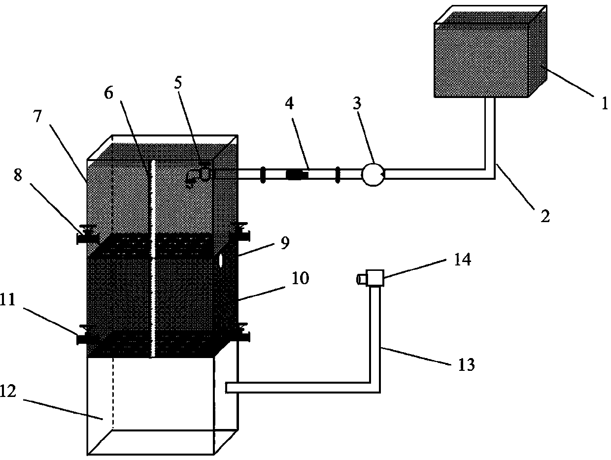
[0005] The purpose of the present invention is to overcome the deficiencies of the prior art, to provide a pipeline dissolution test equipment and test method based on the internal erosion of the soil, which can conveniently control the water level height and water flow velocity, and the pipes with different diameters constructed by dissolving soluble substances such as glucose The pipeline effectively simulates the internal erosion process of the soil. After the pipeline starts to dissolve in the test, the disturbance of the surrounding soil around the pipeline and the settlement and deformation of the surrounding soil can be observed, and it is beneficial to record the moisture content, displacement and porosity during the test. Changes in parameters such as water pressure, so that the cause of the test phenomenon and the correlation with each parameter can be analyzed according to the obtained parameters, thus laying a solid foundation for establishing an appropriate model to predict the soil settlement and disturbance after erosion. It has positive guiding significance for the research on water and soil loss in geotechnical engineering, the prevention of damage caused by internal soil erosion in engineering construction, and the reduction of engineering and non-engineering accidents.

Method used


Image

  • Pipeline dissolution test equipment based on soil internal erosion and test method thereof

Examples


Embodiment

[0035] Embodiment: The erosion test device of this embodiment can be used to observe the disturbance of the surrounding soil and the settlement and deformation of the surrounding soil during the dissolution process of the pipeline, and detect the volume moisture content of rock and soil, pore water pressure, displacement deformation and soil loss rate , the specific test method is as follows:

[0036] S1, configure the initial moisture content sand and soluble glucose powder according to the test plan;

[0037] S2, close the control valve 11 of the erosion generating device to close the through hole at the bottom of the erosion generating device 10, and fill the erosion generating device 10 in layers with an initial moisture content configured according to the test plan at intervals of 10 cm. The sand is compacted and filled well Sprinkle a thin layer of red yarn after each layer of sand, and start to bury a 18mm diameter glucose pipeline at the center of the specified height ...


PUM


Abstract

The invention relates to the technical field of geotechnical engineering, especially to a pipeline dissolution test equipment based on soil internal erosion and test method thereof. The test equipmentcomprises a water supply device, a water collecting device, an erosion generating device, a collecting device, a measuring device and a shooting device. The water collecting device, the erosion generating device and the collecting device have hollow square structures with openings in the tops and are sequentially stacked and overlapped from top to bottom; a glucose pipeline which is vertically arranged is arranged in the middle of an inner cavity of the erosion generating device, and a plurality of moisture content sensors, pore water pressure sensors and displacement sensors are arranged onthe edge of the glucose pipeline. According to the method, a solid foundation is laid for establishing an appropriate model to predict soil settlement and disturbance influence after erosion, and thetest equipment and test method have positive guiding significance in research related to water and soil loss in geotechnical engineering, prevention of harm caused by soil internal erosion in engineering construction, reduction of engineering and non-engineering accidents and the like.

Description

technical field [0001] The invention relates to the technical field of geotechnical engineering, in particular to a pipeline dissolution test device and a test method based on internal erosion of soil. Background technique [0002] In recent years, with the rapid development of urban construction, soil erosion disasters related to ground subsidence and pipelines have increased significantly, and urban road subsidence accidents have increased sharply, which has brought greater safety hazards to urban construction. In this regard, relevant scholars have also carried out a lot of work. The research found that due to the seepage of groundwater, some underground minerals were dissolved, degraded or lost soil particles caused by internal erosion, resulting in a large number of hidden cavities and voids in the strata below the road surface. Pipelines change the soil microstructure, thereby affecting the strength and stiffness of the soil, and are the main cause of a series of probl...

Claims


Application Information

Patent Timeline
Patent Type & Authority Applications(China)
IPC IPC(8): G01N33/24G01N15/08
CPCG01N33/24G01N33/246G01N15/082
Inventor 刘伟平崔运帷何星辰高河
Owner NANCHANG UNIV
Learn More