Pulse shunt

A shunt and pulse technology, used in instruments, voltage/current isolation, measurement devices, etc., can solve problems such as the inability to meet the measurement needs of high pulse current measurement

Pending Publication Date: 2020-04-21
BEIJING DONGFANG MEASUREMENT & TEST INST
View PDF9 Cites 0 Cited by
  • Summary
  • Abstract
  • Description
  • Claims
  • Application Information

AI Technical Summary

Problems solved by technology

Existing pulse shunts cannot meet the measurement

Method used


Image

  • Pulse shunt
  • Pulse shunt
  • Pulse shunt

Examples


Embodiment Construction

[0023] In order to understand the characteristics and technical content of the present application in more detail, the implementation of the present application will be described in detail below in conjunction with the accompanying drawings. The attached drawings are only for reference and description, and are not used to limit the present application.

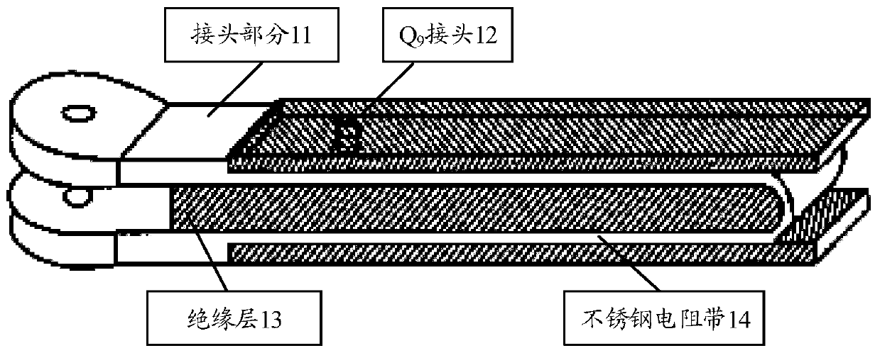
[0024] In one embodiment, using figure 1 The pulse shunt of the folded structure is shown. The pulse shunt of the double-fold structure usually adopts a thin stainless steel resistance. The current end of the pulse shunt is welded with an oxygen-free copper sheet and a stainless steel resistance band, and the core wire of the voltage end is welded with the lower layer of the resistance band. connect. The advantage of the pulse shunt with a folded structure is that it is simple in structure and easy to manufacture, but the pulse shunt with a folded structure has a large residual inductance when it is used, which will bring a l...


PUM


Abstract

The invention discloses a pulse shunt which comprises a shell, a check ring, an insulating sleeve, a current terminal, a current end flange, a locking block, a voltage end flange, a voltage terminal,a resistor insulating tube and a shunt resistor disc. The shell and the shunt resistor disc are of a coaxial structure; two ends of the shunt resistor disc are respectively connected with the currentend flange and the voltage end flange; the locking block is used for pressing the shunt resistor disc, so that the shunt resistor disc is tightly connected with the current end flange and the voltageend flange; the voltage terminal is positioned at the bottom of the pulse shunt; and the resistor insulating tube is positioned in an internal gap of the pulse shunt and is used for supporting the shunt resistor disc so as to keep the overall stability of the pulse shunt.

Description

technical field [0001] The embodiments of the present application relate to current measurement technology, and in particular to the design of a pulse shunt. Background technique [0002] Pulse current measurement technology is a basic science and technology, which is widely used in various fields of national production. The main methods of pulse current measurement are: pulse shunt, current transformer, Rogowski coil, Hall current sensor, photoelectric sensor and other methods. Among them, compared with other testing methods, the pulse shunt has the characteristics of stability, reliability, simple structure, and good linearity, and is widely used in the field of current measurement. Existing pulse shunts cannot meet the measurement requirements for measuring large pulse currents. When using a pulse shunt to measure a large pulse current, the structural design of the shunt has a great influence on the performance of the shunt. Therefore, it is necessary to design the stru...

Claims


Application Information

Patent Timeline
IPC IPC(8): G01R15/14
CPCG01R15/146
Inventor 王书强崔绍颖张军齐潘攀
Owner BEIJING DONGFANG MEASUREMENT & TEST INST
Why Eureka
Try Eureka