
Power supply module

A power module, a pair of technology, applied in the direction of circuits, electrical components, transformer/inductor cores, etc., can solve the problems of enameled wires easy to fuse, difficult to ensure the quality of power modules, and cumbersome operations

Pending Publication Date: 2020-04-21
ZHUHAI HAIWER ELECTRIC APPLIANCE CO LTD
View PDF0 Cites 5 Cited by
  • Summary
  • Abstract
  • Description
  • Claims
  • Application Information

AI Technical Summary

Problems solved by technology

[0004] The transformers used in the power module in the prior art are usually composed of wire turns and magnetic cores, and the wire turns are all enameled wires. During the production and processing of such transformers, the enameled wires need to be wound on the The winding of the transformer on the magnetic core is cumbersome and time-consuming, which is not conducive to production and assembly; at the same time, the transformer needs to be electrically connected to the PCB board on the power module, which requires the transformer to be soldered to the PCB board through each pin of the coil on it. However, the coil pins of this transformer can only be welded to the PCB board by spot welding. Since the transformer has coil pins, only one pin can be welded at a time during welding, which is inefficient, and the enameled wire at the pins is easy to Fuse will reduce the production capacity of the power module, affect the yield of products in mass production, and make it difficult to guarantee the quality of the power module; in addition, due to the structural limitations of the transformer, the transformer and the PCB board are relative to each other in space. Scattered, not conducive to the miniaturization and thinner design of power modules

Method used


Image

  • Power supply module
  • Power supply module
  • Power supply module

Examples


Embodiment Construction

[0022] This part will describe the specific embodiment of the present invention in detail, and the preferred embodiment of the present invention is shown in the accompanying drawings. Each technical feature and overall technical solution of the invention, but it should not be understood as a limitation on the protection scope of the present invention.

[0023] In the description of the present invention, it should be understood that the orientation descriptions, such as up, down, front, back, left, right, etc. indicated orientations or positional relationships are based on the orientations or positional relationships shown in the drawings, and are only In order to facilitate the description of the present invention and simplify the description, it does not indicate or imply that the device or element referred to must have a specific orientation, be constructed and operated in a specific orientation, and thus should not be construed as limiting the present invention.

[0024] I...


PUM


Abstract

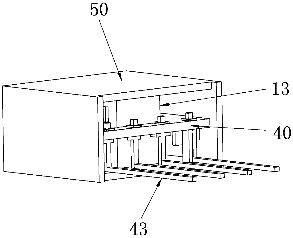
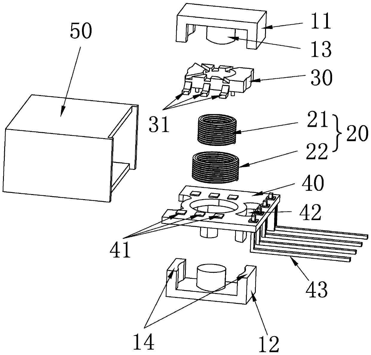
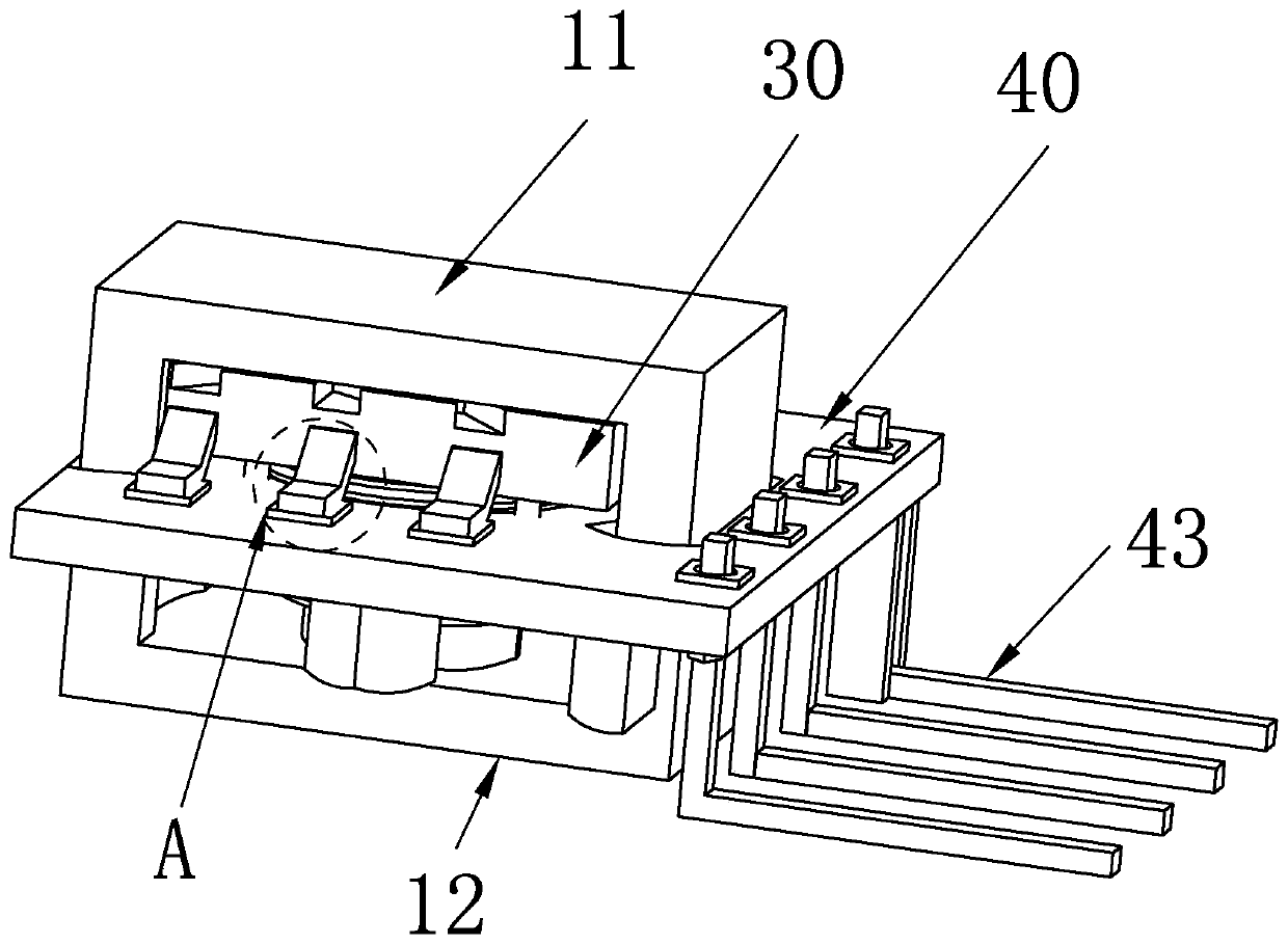
The invention discloses a power supply module. The power supply module comprises a pair of magnetic cores, a coil assembly, a PCB and a wiring base, wherein a magnetic core middle column is arranged between the pair of magnetic cores; the coil assembly is arranged on the magnetic core middle column in a sleeving manner and is provided with a plurality of pins; the PCB is arranged on the coil assembly in the sleeving manner and is provided with a plurality of chip mounting tables; the wiring base is arranged above the PCB and is provided with a plurality of wiring seats correspondingly bindingthe pins, and the wiring seats are in one-to-one correspondence with the chip mounting tables; and the plurality of pins are welded with the plurality of chip mounting tables in a one-to-one correspondence manner. According to the power supply module, full-automatic welding and rapid assembling can be realized; and a traditional mode that the pins on a coil are welded to the PCB through spot welding is omitted, quality problems that enameled wires are fused and broken when the pins of the coil are subjected to spot welding and so on are solved, meanwhile, a requirement for a production and assembly process is simplified, and a capacity of the power module is greatly improved. The whole power supply module is compact in structure, reliability of electronic devices in the module is improved,and design requirements for miniaturization, lightness and thinness of the power supply module in the market are met.

Description

technical field [0001] The present invention relates to the technical field of power supply modules, in particular to a power supply module. Background technique [0002] The power module is a power supply that can be directly mounted on the printed PCB board, and its characteristic is that it can provide power for application-specific integrated circuits, digital signal processors, microprocessors, memories, field programmable gate arrays and other digital or analog loads . Generally, such modules are called point-of-load power supply systems or point-of-use power supply systems. Due to the many advantages of the modular structure, power modules are widely used in switching equipment, access equipment, mobile communications, microwave communications, optical transmission, routers and other communication fields, automotive electronics, aerospace, etc. [0003] Modern electronic systems require electronic devices or components to be smaller, lighter, thinner, and more highl...

Claims


Application Information

Patent Timeline
IPC IPC(8): H01F27/26H01F27/29H01F27/30
CPCH01F27/266H01F27/29H01F27/306
Inventor 王亚东谢德
Owner ZHUHAI HAIWER ELECTRIC APPLIANCE CO LTD
Learn More