Electronic device and communication method

A technology for electronic equipment and user equipment, applied in wireless communication, electrical components, radio transmission systems, etc., can solve the problems of poor applicability, high overhead, and high complexity of joint optimization of digital precoding and analog precoding, and achieve low complexity. Effect

Active Publication Date: 2022-06-24
SONY CORP
View PDF9 Cites 0 Cited by
  • Summary
  • Abstract
  • Description
  • Claims
  • Application Information

AI Technical Summary

Problems solved by technology

In the case of line-of-sight channels, the channel coefficients do not obey the complex Gaussian distribution, and there is a strong correlation between different channels, so the asymptotic orthogonality of large-scale multi-antenna systems is applicable in millimeter-wave frequency band communications poor
Although in communication systems such as millimeter waves, a hybrid precoding architecture can be used to reduce hardware implementation complexity and power consumption, the joint optimization complexity of digital precoding and analog precoding in the hybrid precoding architecture is still very high. lead to high overhead in practical applications

Method used


Image

  • Electronic device and communication method
  • Electronic device and communication method
  • Electronic device and communication method

Examples


example 2

[0141] In Example 1 of Section 4-2, N is obtained by the traditional exhaustive search method opt The complexity is O(M). It can be seen that as the number M of antenna elements increases, the complexity is very high, which imposes a heavy burden on the processing circuit 303 or the activation number acquisition unit 305 and may cause the calculation time to be prolonged improperly. It is beneficial to improve the efficiency of the communication system.

[0142] In this case, if the requirements for the results are not particularly strict, the number N of activated antenna elements that make B(N,φ) less than the set threshold η can be directly used in the first search. sub-opt , to be used for downlink beamforming, instead of selecting N that minimizes B(N,φ) from the final set obtained through multiple searches sub-opt . This is a way to reduce complexity, but it may not be possible to obtain N that minimizes B(N,φ) sub-opt .

[0143] In order to reduce the complexity and...

example 3

[0149] In the foregoing determination example 1 and determination example 2, the number of activated antenna elements is calculated in real time. Although we have come up with a way to reduce complexity through simulation, it still incurs real-time computational resource and time overhead.

[0150] In this example 3, a method is proposed to avoid the overhead of real-time computing resources and time by pre-static configuration.

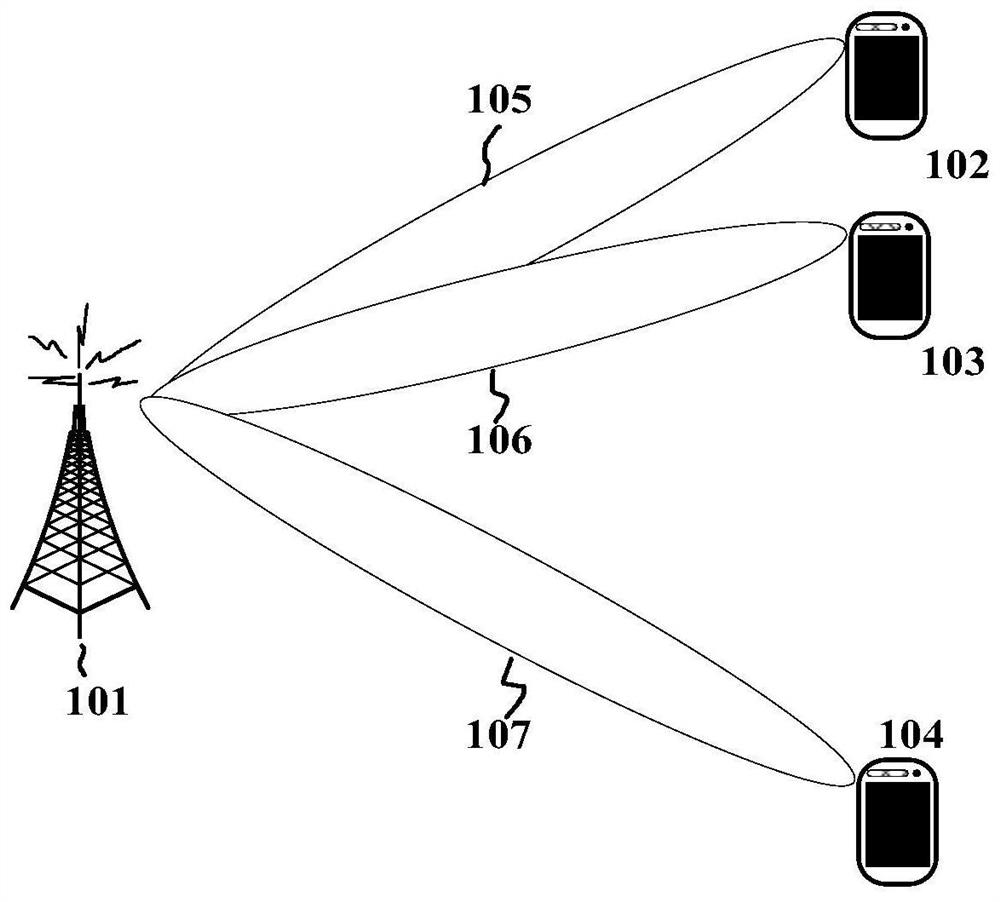
[0151] Specifically, the beamforming codebook, such as the DFT codebook, is fixed, so the pointing directions (beam directions) of each transmit beam generated by the base station are relatively fixed, so the base station 101 and the user equipments 102-104 can know Beam direction of each transmit beam.

[0152] Since the beam direction representing the direction of the downlink transmitted signal can be known in advance, then directly using the calculation algorithm in the determination example 1 and the determination example 2, the corresponding r...


PUM


Abstract

An electronic device and communication method. The electronic device includes a processing circuit configured to: determine that signal transmission is simultaneously performed to at least two user equipments and the proximity of directions of downlink transmission signals used for the at least two user equipments satisfies a predetermined condition; and acquire The number of activated antenna elements used for downlink beamforming determined based on directions of downlink transmit signals for the at least two user equipments.

Description

[0001] CROSS-REFERENCE TO RELATED APPLICATIONS [0002] The present disclosure claims priority to Chinese Patent Application No. 201710820287.6 filed on September 13, 2017, the disclosure of the above Chinese Patent Application is hereby incorporated by reference in its entirety as a part of the present disclosure. technical field [0003] The present disclosure generally relates to an electronic device and communication method, and more particularly, to an electronic device and communication method for a millimeter-wave massive multi-antenna system. Background technique [0004] As one of the key technologies of next-generation wireless communication (5G), Massive multiple-input multiple-output (Massive MIMO) technology has attracted extensive attention. As the number of antennas in a large-scale multi-antenna system increases, each channel coefficient tends to be orthogonal, and this property is hereinafter referred to as asymptotic orthogonality. Benefiting from the asym...

Claims


Application Information

Patent Timeline
Patent Type & Authority Patents(China)
IPC IPC(8): H04B7/0408H04B7/06H04B7/08
CPCH04B7/0413H04B7/0617H04W16/28H04B7/0452H04B7/0608H04B7/0417
Inventor 刘文东王昭诚曹建飞
Owner SONY CORP
Why Eureka
Try Eureka