Impeller and low-noise emulsifying pump
A technology of impeller and gear, which is applied in the field of emulsification pumps, can solve problems such as high noise, and achieve the effects of reducing pressure difference, reducing sound and reducing friction
- Summary
- Abstract
- Description
- Claims
- Application Information
AI Technical Summary
Problems solved by technology
Method used
Image
Examples
Embodiment 1
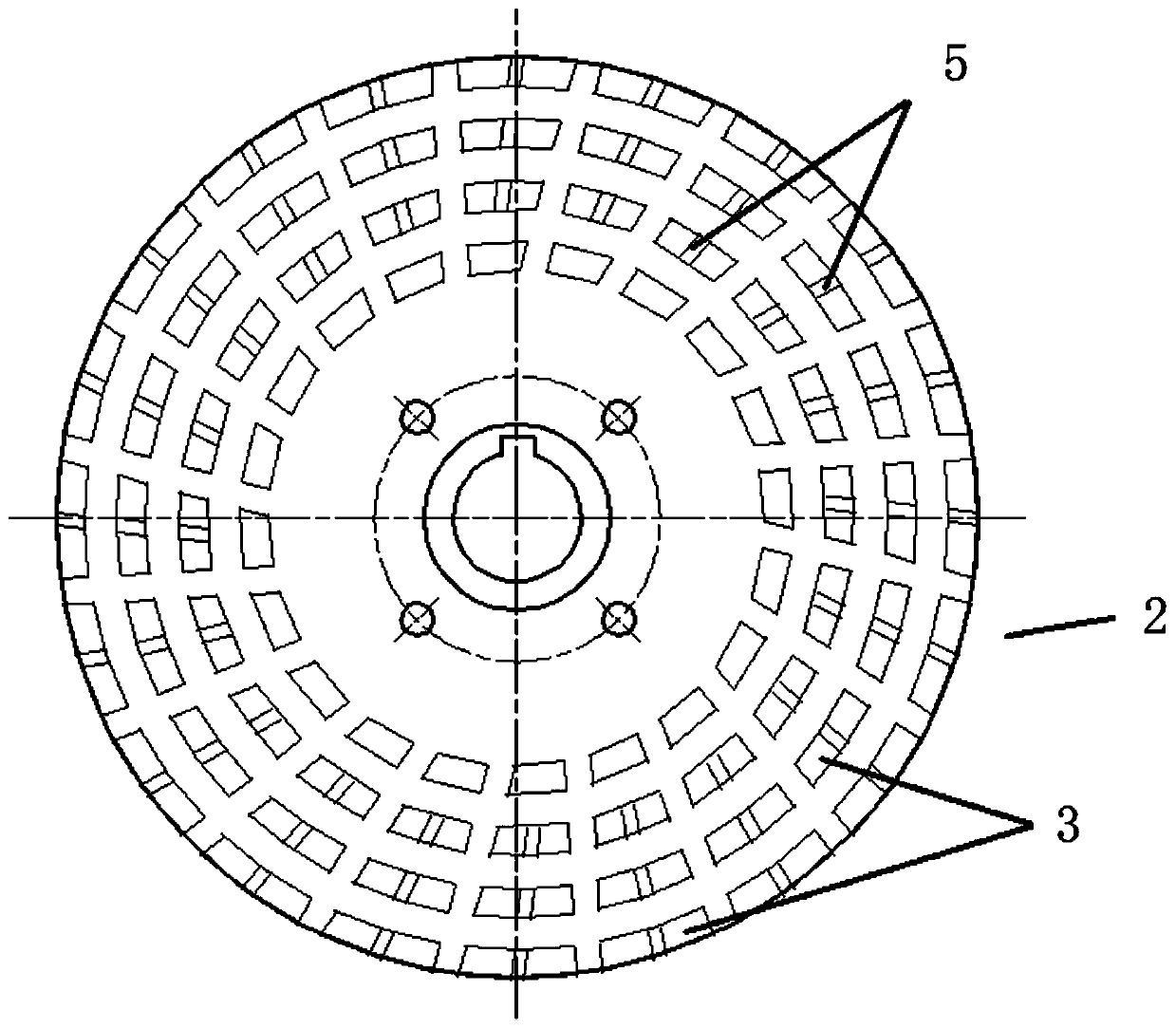
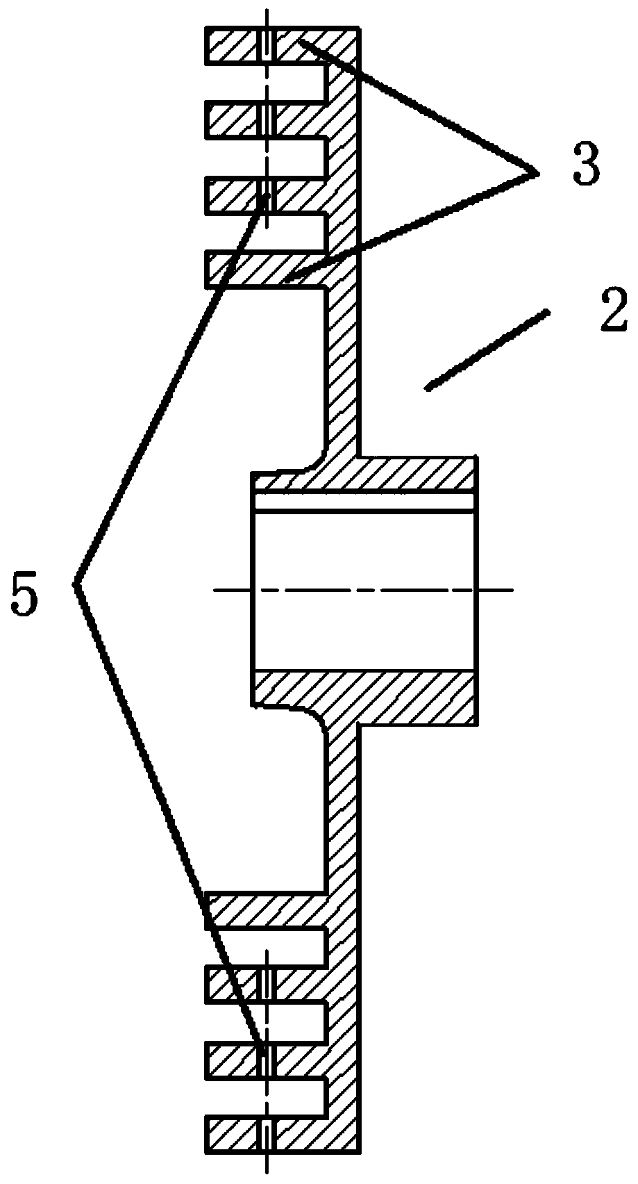
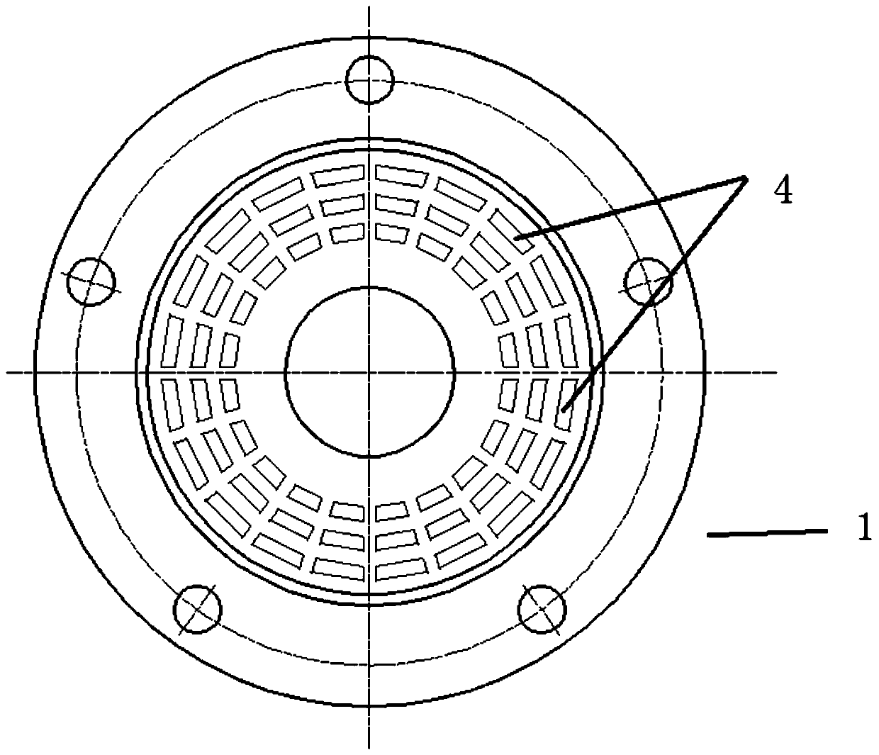
[0031] The impeller in this embodiment, such as figure 1 As shown in -4, it includes a stator 1 and a rotor 2 coupled with the stator 1 .
[0032] Such as figure 1 and figure 2 As shown, the rotor 2 is provided with four circles of shearing plates 3 around the axis of the stator 1, and the other three circles of the shearing plates 3 except the innermost circle of the shearing plates 3 are all provided with the Described decompression channel 5.
[0033] In order to increase the stability of the rotor 2 , a decompression channel 5 is provided at the middle of the shear piece 3 . In this embodiment, the decompression channel 5 is a through hole, the axis of the through hole intersects with the axis of the stator 1, and the connection line between two adjacent decompression channels 5 in two adjacent turns and the The axes of the stator 1 intersect.
[0034] The stator 1 is provided with three rings of teeth 4 around the axis of the stator 1 , and the shearing pieces 3 and...
Embodiment 2
[0038] The impeller in this embodiment, such as Figure 5 As shown, it includes a stator 1 and a rotor 2 coupled with the stator 1 .
[0039] The stator 1 is provided with three rings of gears 4 around the axis of the stator 1 , and the decompression channels 5 are provided on the three rings of the teeth 4 .
[0040] In order to increase the stability of the stator 1 , a decompression channel 5 is provided at the middle of the tooth piece 4 . In this embodiment, the decompression channel 5 is a through hole, the axis of the through hole intersects with the axis of the stator 1, and the connection line between two adjacent decompression channels 5 in two adjacent turns and the The axes of the stator 1 intersect.
[0041] The rotor 2 is provided with four turns of shearing plates 3 around the axis of the stator 1 , and the shearing plates 3 and the tooth plates 4 are overlapped. When the fluid is homogenized, sheared, and emulsified through the coupled stator 1 and the rotor...
Embodiment 3
[0045] The impeller in this embodiment, such as Figure 6As shown, it includes a stator 1 and a rotor 2 coupled with the stator 1 . The stator 1 is provided with three rings of teeth 4 around the axis of the stator 1, and the rotor 2 is provided with four rings of shear plates 3 around the axis of the stator 1. The tooth pieces 4 are staggered, and the shearing pieces 3 and the tooth pieces 4 are staggered along the radial direction of the stator 1 . The decompression channels 5 are alternately arranged on the shear piece 3 and the tooth piece 4 . Such as Figure 6 As shown, from the inner side to the outer side, a decompression channel 5 is provided on the shear piece 3 of the fourth circle, and a decompression channel 5 is provided on the tooth piece 4 of the second circle. Of course, the decompression channel 5 can also be set in other ways according to usage requirements.
PUM
 Abstract
Description
Claims
Application Information
 - R&D
- Intellectual Property
- Life Sciences
- Materials
- Tech Scout
- Unparalleled Data Quality
- Higher Quality Content
- 60% Fewer Hallucinations
Browse by: Latest US Patents, China's latest patents, Technical Efficacy Thesaurus, Application Domain, Technology Topic, Popular Technical Reports.
© 2025 PatSnap. All rights reserved.Legal|Privacy policy|Modern Slavery Act Transparency Statement|Sitemap|About US| Contact US: help@patsnap.com


