Pipe laser welding machine

A laser welding machine and welding mechanism technology, applied in laser welding equipment, welding equipment, metal processing equipment and other directions, can solve the problems of poor welding effect, poor welding efficiency, high content of carbon and alloy elements, and achieve good welding effect, Good positioning effect

Active Publication Date: 2020-04-24
武汉大族金石凯激光系统有限公司
View PDF13 Cites 3 Cited by
  • Summary
  • Abstract
  • Description
  • Claims
  • Application Information

AI Technical Summary

Problems solved by technology

[0002] With the continuous advancement of my country's car lightweight work, the demand for high-strength welded pipes for car torsion beams is increasing year by year. Due to the high content of carbon and alloy elements in high-strength welded pipes, the high-frequency resistance welding metho

Method used


Image

  • Pipe laser welding machine
  • Pipe laser welding machine
  • Pipe laser welding machine

Examples


Embodiment Construction

[0034] The present invention will be further described below through specific embodiments, but the present invention is not limited to the following specific embodiments.

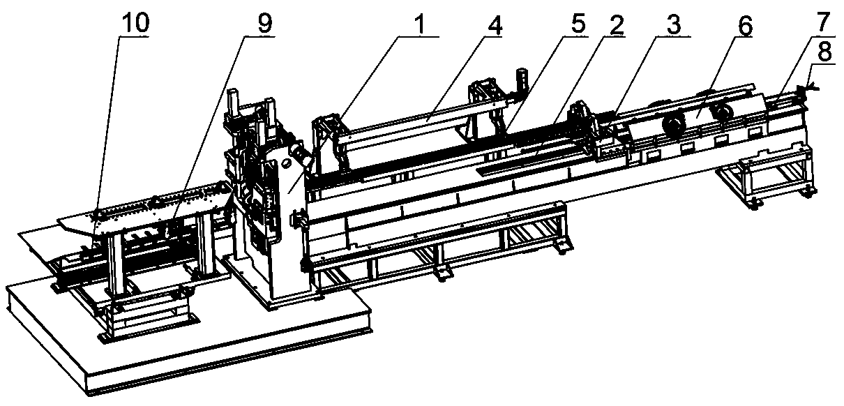
[0035] A pipe laser welding machine, including a controller, a feeding mechanism, a main engine, a material discharging mechanism, a safety protection mechanism and an auxiliary mechanism, and the main engine includes a frame 1 and a pre-positioning mechanism, a positioning mechanism and a welding mechanism arranged on the frame 1 ,in:

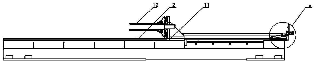
[0036] The feeding mechanism includes the feeding slide 2, the pre-feeding structure, the hanger 4, the pendant 5 and the pushing fixture 3, wherein:

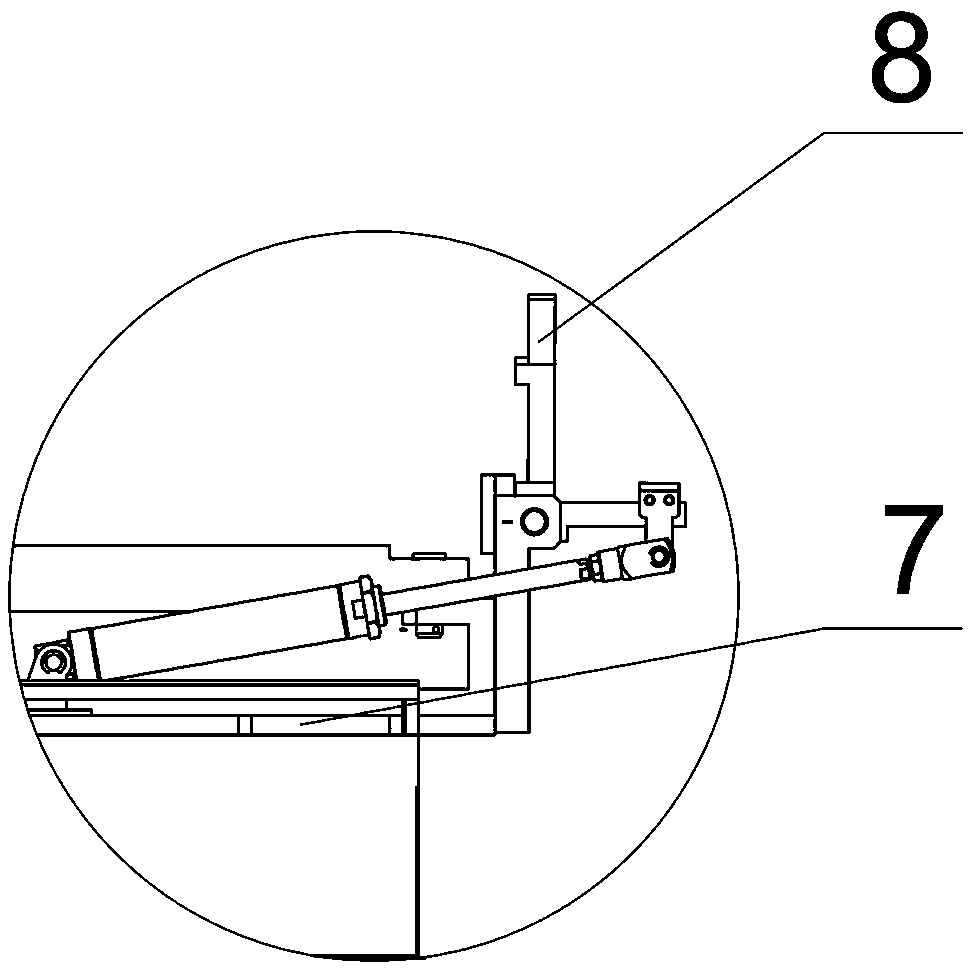
[0037] The pre-feeding structure includes a shift fork seat 7 slidingly connected on the feed slide 2, a telescopic rod, an L-shaped connecting rod, a shift fork 8 and a power mechanism. The shift fork seat 7 includes a horizontal part and a vertical part, and the L-shaped connection The rod corner position is connected to ...


PUM


Abstract

The invention relates to the technical field of welding, in particular to a pipe laser welding machine which includes a controller, a feeding mechanism, a main machine, and a discharging mechanism. The main machine is provided with a positioning mechanism and a welding mechanism, the feeding mechanism, the positioning mechanism, the welding mechanism, and the discharging mechanism are all in signal connection with the controller, wherein the feeding mechanism includes a feeding slide platform (2) and a material pushing fixture (3) slidably connected to the feeding slide platform (2), and the material pushing fixture (3) is connected to the controller in a signal mode; the positioning mechanism includes a five-roller positioning mechanism, and the five-roller positioning mechanism is in signal connection with the controller; the welding mechanism includes a fiber laser and a welding head (26), and the fiber laser is in signal connection with the controller; and the discharging mechanismincludes a pipe outlet manipulator (9) and a pipe unloading device (10), and the pipe outlet manipulator (9) and the pipe unloading device (10) are all connected with the controller in a signal mode.The pipe laser welding machine is higher in welding efficiency and better in welding effect.

Description

technical field [0001] The invention relates to the field of welding technology, in particular to a pipe laser welding machine. Background technique [0002] With the continuous advancement of my country's car lightweight work, the demand for high-strength welded pipes for car torsion beams is increasing year by year. Due to the high content of carbon and alloy elements in high-strength welded pipes, the high-frequency resistance welding method of the existing technology cannot meet the quality requirements. and quality reliability requirements. [0003] Although the prior art also uses a laser welding machine to weld high-strength steel pipes, the laser welding machine of the prior art has poor welding efficiency and poor welding effect. Contents of the invention [0004] The technical problem to be solved by the present invention is to provide a pipe laser welding machine with high welding efficiency and good welding effect. [0005] The technical solution adopted in th...

Claims


Application Information

Patent Timeline
IPC IPC(8): B23K26/21B23K26/08B23K26/142B23K26/70
CPCB23K26/0869B23K26/14B23K26/142B23K26/21B23K26/703
Inventor 黄昭明李光彭磊刘千军
Owner 武汉大族金石凯激光系统有限公司
Why Eureka
Try Eureka