Automatic rubbing ball feeding device

An automatic feeding and rubbing technology, which is applied in the direction of spherical grinder, transportation and packaging, grinding feed movement, etc., can solve the problems of difficult workpiece positioning, movement, difficult operation, high scrap rate, etc., and achieve accurate feeding position , Reduce labor and save cost

Active Publication Date: 2020-04-24
DALIAN DEMAISHI PRECISION TECH CO LTD +1
View PDF5 Cites 2 Cited by
  • Summary
  • Abstract
  • Description
  • Claims
  • Application Information

AI Technical Summary

Problems solved by technology

For example, ball processing parts, due to the small size of these workpieces and the precise requirements of the feeding position, these workpieces are difficult to locate and move, which brings many difficulties to the operation
In particular, the surface of the workpiece to be processed is arc-shaped. Due to frequent deviations in manual placement, the rate of scrap parts during processing is high, which seriously affects production efficiency. At the same time, it also imposes a workload on operators.

Method used


Image

  • Automatic rubbing ball feeding device
  • Automatic rubbing ball feeding device
  • Automatic rubbing ball feeding device

Examples


Embodiment Construction

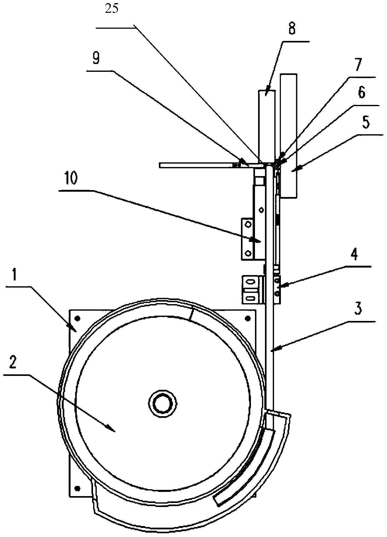
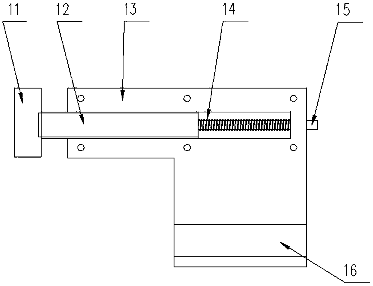
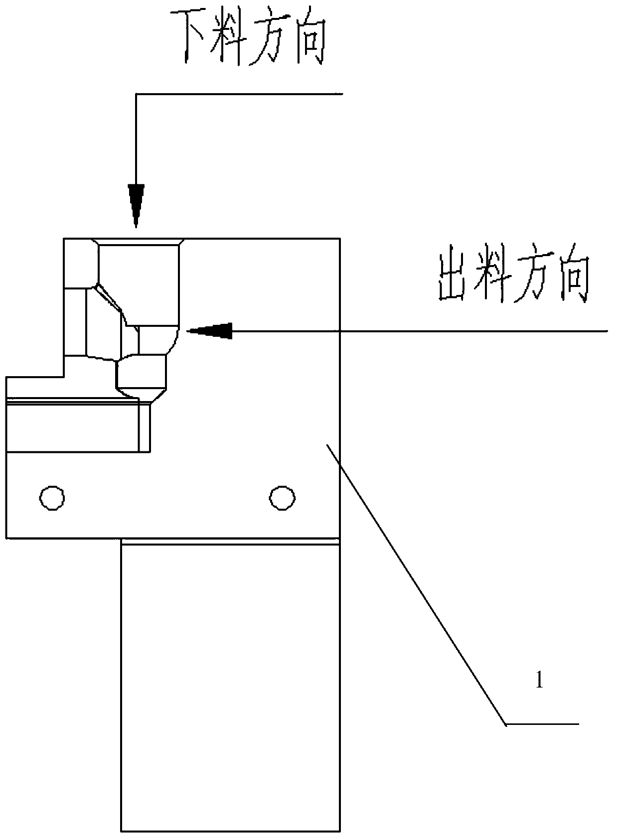
[0024] exist Figure 1 to Figure 6 In the schematic diagram of the present invention shown, a vibrating disc 2 is arranged on the vibrating disc frame body 1, the discharge port of the vibrating disc is connected with the elbow 3, the spherical surface to be processed 6 passes through the elbow, and the spherical surface is to be processed The bottom of the part is placed in the bracket 25, that is, the A position 26 in the bracket. The two side walls at the position of bracket A are arc-shaped surfaces, and the tightening mechanism 10 is placed on one side of the push plate 9 of the machine tool, and the tightening mechanism is fixed on the bed body. The tightening mechanism includes a tightening and fixing block 11 , a tightening and fixing block connecting plate 12 , a fixing frame 13 , a spring A14 , a spring connecting rod 15 and a fixing seat 16 . The tightening mechanism is arranged on one side of the push plate of the machine tool, and the fixing seat of the tightenin...


PUM


Abstract

The invention discloses an automatic rubbing ball feeding device. The automatic rubbing ball feeding device mainly comprises a vibrating disc frame body, a vibrating disc, a bent pipe, a pushing mechanism, a movable rubbing plate, to-be-machined parts of a spherical surface, a supporting plate, a fixed rubbing plate, a machine tool pushing plate and a clamping mechanism, wherein the vibrating discis arranged on the vibrating disc frame body, the discharging opening of the vibrating disc is connected with the bent pipe, the the to-be-machined parts of the spherical surface passe through the bent pipe, and the bottoms of the to-be-machined parts of the spherical surface are arranged in a support groove, namely, the bottom of the to-be-machined parts of the spherical surface are arranged onthe A position in the support groove. The device can achieve automatic feeding, the feeding position is accurate, and the device does not deviate in the feeding movement process. The to-be-machined parts of the spherical surface can be guaranteed to fall into the A position of the support groove, the to-be-machined parts of the spherical surface can be guaranteed to move to the joint of the feeding end of the support plate and the discharging end of the support groove, the position is accurate, and deviation and dumping cannot occur. When one end of a material ejecting rod and one end of an adjusting plate simultaneously push the upper parts and the lower parts of the to-be-machined parts of the spherical surface to move, the to-be-machined parts of the spherical surface can move stably inthe support plate without deviating and dumping.

Description

technical field [0001] The invention relates to the processing field, in particular to a feeding device. Background technique [0002] When processing and assembling in the mechanical field, it is often necessary to load some smaller workpieces. For example, spherical workpieces, due to the small size of these workpieces and the precise requirements of the feeding position, these workpieces are difficult to locate and move, which brings many difficulties to the operation. In particular, the surface of the workpiece to be processed is arc-shaped. Due to frequent deviations in manual placement, the rate of scrap parts during processing is very high, which seriously affects production efficiency. At the same time, it also imposes a workload on operators. Contents of the invention [0003] The object of the present invention is to provide an automatic feeding device for rubbing balls, which can automatically load materials, and has a precise feeding position and no deviation ...

Claims


Application Information

Patent Timeline
Patent Type & Authority Applications(China)
IPC IPC(8): B24B11/02B24B41/00B24B41/04B65G47/14B65G47/82
CPCB24B11/02B24B41/005B24B41/04B65G47/1421B65G47/82
Inventor 胡善成
Owner DALIAN DEMAISHI PRECISION TECH CO LTD
Why Eureka
Try Eureka