Rack system for digital printing machines

A digital printing machine and frame technology, applied in printing, printing devices, separation methods, etc., can solve the problems of unsatisfactory cloth lint cleaning effect, no waste water recycling system, and inconvenient adjustment of counterweight blocks, etc., to achieve structural Compact, avoid work with water, improve the effect of printing quality

Active Publication Date: 2021-06-22
广东希望高科数字技术有限公司
View PDF8 Cites 0 Cited by
  • Summary
  • Abstract
  • Description
  • Claims
  • Application Information

AI Technical Summary

Problems solved by technology

[0003] However, the rack system of the existing digital printing machine has the following technical problems: (1) it needs to be equipped with a separate cloth frame; (2), the edge-aligning device only aligns the edge during the cloth-running process, and requires a lot of space to Buffering; (3) The position of the moving roller is fixed, and there is no chance to eliminate the creases of the cloth during printing; (4) The moving roller does not have a heating device, so that the cloth can be more closely attached to the printing conveyor belt; (5) It is inconvenient to adjust the counterweight of the constant tension mechanism, because there are too many types of fabrics, and the adaptability of the counterweight is not necessarily suitable for the used one. The fabric needs to be adapted and adjusted frequently; and the cylinder installed at both ends of the constant tension roller, due to the inevitable reality difference in the quality of the cylinder, it is difficult to control the balance of the force on both sides, and it is prone to jamming; (6) Cleaning means The combination is relatively simple, and the cleaning effect on the cloth lint sticking to the surface of the conveyor belt is not ideal; (7) The water consumption is large, the waste water discharge is large, and there is no waste water recycling system, which is not conducive to energy saving and environmental protection

Method used


Image

  • Rack system for digital printing machines
  • Rack system for digital printing machines
  • Rack system for digital printing machines

Examples


Embodiment Construction

[0062] The present invention and its beneficial technical effects will be further described in detail below in conjunction with the accompanying drawings and preferred embodiments.

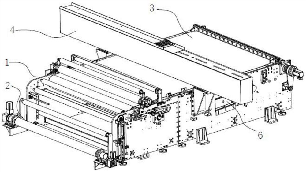
[0063] see Figure 1~Figure 2 The frame system of the digital printing machine preferably implemented in the present invention comprises a frame 1 and a cloth upper mechanism 2 arranged on the frame, a printing conveying belt mechanism 3, a gantry carriage 4, a belt cleaning device 6; a printing conveying belt mechanism 3 It is arranged on the top of the frame, the gantry carriage 4 spans above the printing conveying belt mechanism 3, the cloth loading mechanism 2 is arranged behind the printing conveying belt mechanism 3, and the belt cleaning device 6 is arranged below the printing conveying belt mechanism 3; characterized in that,

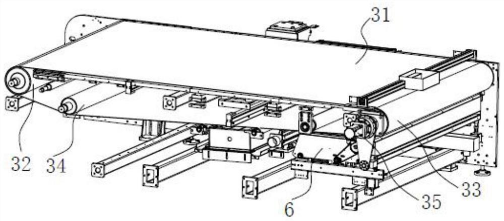
[0064] Described printing conveying belt mechanism 3 comprises transmission belt 31, driving drum 33, driven drum 32, belt deviation correction roller 34 and belt ...


PUM


Abstract

The invention discloses a frame system of a digital printing machine, which comprises a frame, a printing conveying belt mechanism is arranged on the top of the frame, a gantry carriage spans above the printing conveying belt mechanism, and a cloth loading mechanism is arranged on the printing conveying belt mechanism The belt cleaning device is set at the bottom of the printing conveying belt mechanism; the cloth loading mechanism includes an air expansion shaft, a large roll angle roller, a cloth passing roller a, a constant tension floating roller, and a cloth passing roller all arranged on the frame. b. Cloth passing roller c, moving roller, widening angle wrapping roller; equipped with lifting and guiding mechanism to drive constant tension floating roller; equipped with unwinding and deviation correcting system for correcting the position of the cloth. Its advantages are: the cloth feeding mechanism adapts to large and small rolls of cloth at the same time, saving costs; the cloth is automatically corrected online and aligned in real time; the printing quality is high; the belt cleaning device adopts a combination of compound cleaning mode and compound drying, which improves the cleaning effect; water consumption is small and energy saving Environmental protection; production efficiency improvement.

Description

technical field [0001] The invention relates to a scanning digital printing machine, in particular to a frame structure of the scanning digital printing machine. Background technique [0002] Scanning digital printing machines are widely used in clothing, cutting pieces, clothing, leather, luggage, transfer paper, artificial flowers, shoe materials, flocking cloth, thick plate, cloth, etc. At present, the frame system of a digital printing machine includes a frame and a cloth loading mechanism arranged on the frame, a printing conveying belt mechanism, a gantry carriage, and a belt cleaning device; The large roll wrapping roller, the cloth passing roller, the constant tension roller, the pressure roller and the widening corner wrapping roller on the frame; the frame is equipped with a device for aligning the fabric; the constant tension roller is equipped to maintain the tension The constant tension mechanism adopts counterweights or cylinders are installed at both ends of ...

Claims


Application Information

Patent Timeline
Patent Type & Authority Patents(China)
IPC IPC(8): B41J29/00B41J29/17B01D29/03
CPCB41J29/17B41J29/00B01D29/03B65H20/06B65H23/16B65H20/02B65H2701/1133B65H2701/174B65H2301/531B65H2801/03
Inventor 何小燕
Owner 广东希望高科数字技术有限公司
Why Eureka
Try Eureka