
Stacking machine and fork positioning method thereof

A stacker and pallet fork technology, which is applied in the field of automated material transportation, can solve the problems that the cargo 72 cannot be fed in, the deformation amount is different, and the pallet fork 71 cannot be accurately inserted into the target position of the shelf, etc.

Active Publication Date: 2020-04-24
广东瑞仕格科技有限公司
View PDF8 Cites 6 Cited by
  • Summary
  • Abstract
  • Description
  • Claims
  • Application Information

AI Technical Summary

Problems solved by technology

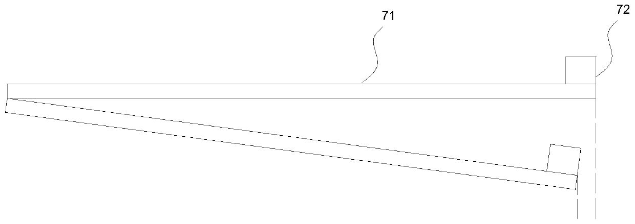
[0004] However, in the actual operation process, there are the following problems: please refer to figure 1 , when the fork 71 stretches out to pick up and release the material, the weight of the cargo 72 will cause the fork 71 to bend downward, because of the difference in load (empty load when taking material, heavy load when discharging), the fork 71 The deformation amount will also be different
The expansion and contraction of the fork 71 is positioned according to the position fed back by the fork position encoder. Although the position fed back by the fork encoder is consistent, in fact, due to the generation of deformation, the actual extension of the fork 71 when loading There is a large deviation in the length, so during the process of frequent loading and unloading of the fork 71 in the vertical warehouse, the deviation of the protruding length of the fork 71 will continue to accumulate, and the relative position of the goods on the fork 71 will gradually shift, eventually causing the goods The fork 71 cannot be accurately extended into the target position of the shelf, that is, the goods 72 cannot be normally sent into the position of the shelf

Method used


Image

  • Stacking machine and fork positioning method thereof
  • Stacking machine and fork positioning method thereof
  • Stacking machine and fork positioning method thereof

Examples


specific Embodiment approach 2

[0057] Please also refer to Figure 7 to Figure 9 The difference between this embodiment and the first embodiment is that the load detection module 8 mainly includes a tension sensor 81 , a fastening bolt 83 and a pressing block 85 .

[0058] In this embodiment, the tension sensor 81 includes a housing 811 and two supporting parts 813 protruding from the same side of the housing 811, each supporting part 813 is provided with a slot 801 for clamping the wire rope 35, The compression block 85 is sleeved on the outer periphery of the housing 811 and is located between the two supporting parts 813. There is a gap between the compression block 85 and the housing 811 for the wire rope 35 to pass through. The compression block 85 and the fastening bolt 83 are connected to tighten the wire rope 35. During the working process, due to the effect of the fastening bolt 83, the steel wire rope 35 is kept in a tensioned state. The steel wire rope 35 has pressure on the support portion 813...


PUM


Abstract

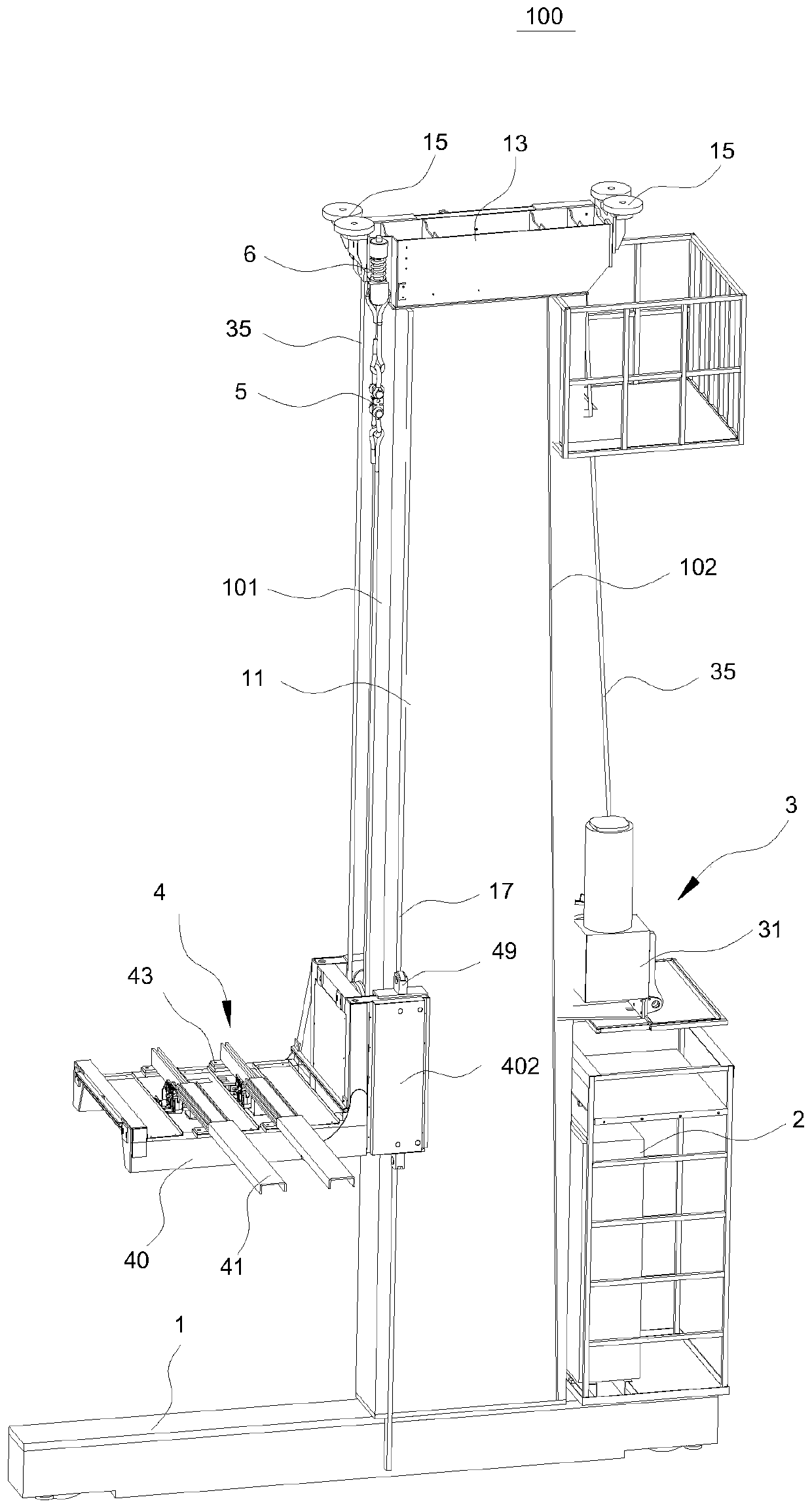
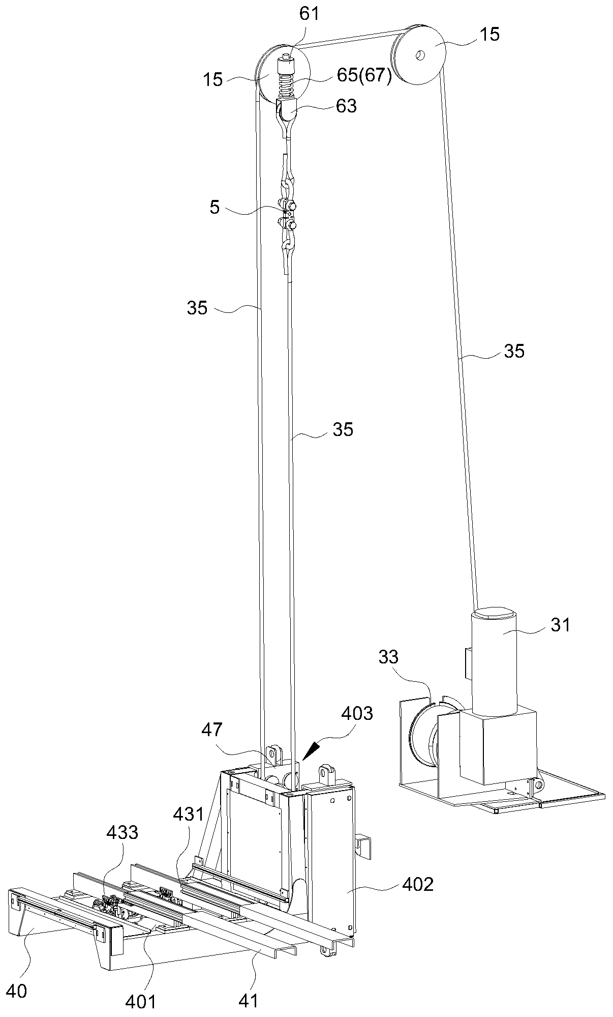
The invention provides a stacking machine and a fork positioning method thereof. A lifting module in the stacking machine is used for lifting a cargo carrying table, and specifically the cargo carrying table is pulled by a steel wire rope to vertically ascend and descend along stand columns; a load detection module is arranged on the steel wire rope and can detect the weight of cargos on the cargocarrying table in real time; and the controller can calculate the deformation quantity of a fork according to the weight of the cargos and then calculate the extension length, needing to be compensated for, of the fork according to the deformation quantity, so that the normal use requirement of the fork for taking and placing the cargos is met. The stacking machine is simple in structure and convenient to install, dynamic compensation for the extending length of the fork can be achieved, the positioning error of the fork is reduced, and the cargo placing precision is improved.

Description

technical field [0001] The invention relates to the technical field of automatic material transportation, in particular to a stacker and a positioning method for its forks. Background technique [0002] At present, with the widespread use of automated three-dimensional warehouses in the logistics industry, the demand for the use of stackers has increased significantly. [0003] A stacker is an automatic material handling machine that uses forks to move, stack, and pick and place goods from high-rise shelves. For example, the double-deep stacker is more flexible. One stacker can pick and place the materials on the left and right rows of shelves, and through the flexible switching and superposition of two forks, the goods at a higher position can be picked up. [0004] However, in the actual operation process, there are the following problems: Please refer to figure 1 , when the fork 71 stretches out to pick up and release the material, the weight of the cargo 72 will cause ...

Claims


Application Information

Patent Timeline
IPC IPC(8): B66F9/075B66F9/08B66F9/12B66F9/18B66F9/24B66F17/00
CPCB66F9/07559B66F9/0759B66F9/08B66F9/122B66F9/18B66F9/24B66F17/003
Inventor 李福来
Owner 广东瑞仕格科技有限公司
Learn More