Compression release type engine in-cylinder braking system

A technology for engine cylinders and braking systems, applied in engine control, engine components, machines/engines, etc., to solve problems such as limitations and complex structures

Pending Publication Date: 2020-04-24
WEIFANG LICHUANG ELECTRONICS TECH
View PDF2 Cites 7 Cited by
  • Summary
  • Abstract
  • Description
  • Claims
  • Application Information

AI Technical Summary

Problems solved by technology

Since the normal running state accounts for most of the running state of the entire engine, the gap compensation mechanism is in the working state for most of the time when the engine is running, which puts forward higher requirements for reliability, etc., and the structure is more complicated
[0005] For this reason, the applicant has developed a new type of engine in-cylinder braking device, and submitted a patent application with the notification number CN110566309A titled "compression release type engine in-cylinder braking device", but in subsequent practical applications, the applicant It is found that there are the following problems that need to be further improved: the structure is too complex and can only be applied to multi-cylinder engines with an even number of engine cylinders, and each cylinder of the engine must have a corresponding cylinder with a phase of 360° crank angle, so the application is limited

Method used


Image

  • Compression release type engine in-cylinder braking system
  • Compression release type engine in-cylinder braking system
  • Compression release type engine in-cylinder braking system

Examples


Embodiment 1

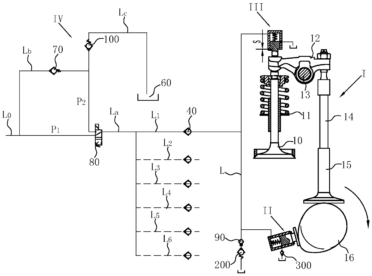
[0059] Such as figure 1 As shown, the compression-release engine in-cylinder braking system according to Embodiment 1 of the present invention is applied to the valve train I of the engine, and includes: oil pump device II, oil cylinder device III and oil supply device IV.

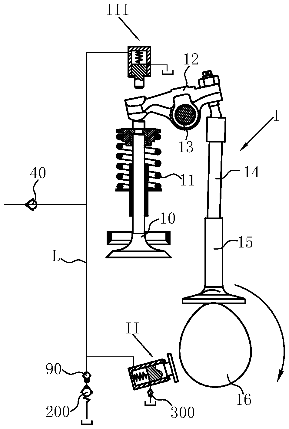
[0060] Wherein, the rocker arm 12 of gas distribution mechanism 1 is rotatably installed on the rocker shaft 13, and the push rod 14 and the valve 10 are respectively placed on both sides of the rocker shaft 13. When the rocker arm 12 is pushed from one side to swing around the rocker shaft 13, the other side of the rocker arm 12 presses the valve 10, and the valve opens; Return, the valve is closed. The above is the process for controlling valve action in its valve train 1 when the engine is running normally.

[0061] Such as Figure 4 As shown, the oil supply device IV includes an oil supply oil passage La, a decompression oil passage Lb, a pressure relief oil passage Lc and an electromagnetic reversi...

Embodiment 2

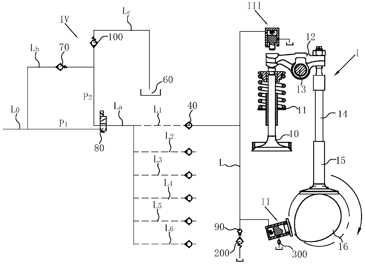
[0089] Such as Figure 10 As shown, the compression release type engine in-cylinder braking system of the second embodiment of the present invention is basically the same as the first embodiment, the difference is that the cam used to lean against and push the plunger 22 of the oil pumping device II is an overall The brake cam 16a, the total brake cam 16a is a cam added at the appropriate position on the camshaft, which is different from the original exhaust cam and intake cam on the camshaft; and, the oil pumping device II corresponding to all cylinders of the engine Arranged around the total brake cam 16a, the number of oil pumping devices II is the same as the number of cylinders of the engine.

[0090] Such as Figure 10 Taking a six-cylinder engine as an example, it shows that the oil pumping device II of the six cylinders of the engine is arranged around the total braking cam 16a.

[0091] Obviously, the compression release engine in-cylinder braking system of the pres...


PUM


Abstract

The invention discloses a compression release type engine in-cylinder braking system. The system involves a gas distribution mechanism, oil cylinder devices, oil pumping devices and an oil supplying device, wherein all air cylinders share the oil supplying device, each of the air cylinders is provided with one oil cylinder device and one oil pumping device which communicates through a pressure transmission oil path, and the pressure transmission oil path communicates with the oil supplying device through a one-way valve; during in-cylinder braking, an electromagnetic reversing valve is energized, engine oil with the pressure P1 is supplied to the pressure transmission oil path, a cam abuts against and pushes the pumping devices, high-pressure oil is pumped to the oil cylinder devices to push a rocker arm to open a valve, and in-cylinder braking is achieved; during non-cylinder braking, the electromagnetic reversing valve is powered off, engine oil with the pressure P2 is supplied to the pressure transmission oil path, P1 is greater than P2, the oil cylinder devices and the oil pumping devices are returned correspondingly, and the cam is disengaged from the pumping devices. The compression release type engine in-cylinder braking system is stable and reliable in work and low in failure rate, moreover, the braking system is simple in structure, is not limited by the number of engine cylinders, and is wide in application range.

Description

technical field [0001] The invention relates to the technical field of engine variable valves, in particular to a compression release type engine in-cylinder braking system. Background technique [0002] During the normal operation of the engine, every time the camshaft rotates 360°, the engine completes four working cycles of intake, compression, work and exhaust. At the end of the compression stroke, fuel is burned in the cylinder to do work in the subsequent expansion stroke. [0003] Engine in-cylinder braking is a form of vehicle auxiliary braking. The contribution of engine in-cylinder braking is that it can not only improve the braking capacity of the vehicle, but also reduce the braking load of the main brake of the vehicle. When braking in the engine cylinder, the compression stroke engine does auxiliary power to the outside. When the compression stroke is close to the top dead center, driven by the brake device in the engine cylinder, the exhaust valve is opened f...

Claims


Application Information

Patent Timeline
Patent Type & Authority Applications(China)
IPC IPC(8): F01L13/06F01L9/02F02D13/04F01L1/047F01L9/10
CPCF01L13/065F02D13/04F01L1/047F01L9/10
Inventor 王立峰王秀强吴龙龙王孟晓王昊天吴贝贝从田增吴鹏超苏明涛衣金水
Owner WEIFANG LICHUANG ELECTRONICS TECH
Why Eureka
Try Eureka