
Full-premixing condensation boiler

A condensing boiler, fully premixed technology, applied in air heaters, fluid heaters, sustainable buildings, etc., can solve problems such as low thermal efficiency and heat loss

Pending Publication Date: 2020-04-24
喀什翰明燃气设备有限公司
View PDF0 Cites 7 Cited by
  • Summary
  • Abstract
  • Description
  • Claims
  • Application Information

AI Technical Summary

Problems solved by technology

[0003] A general fully premixed condensing boiler includes a burner and a heat exchanger. The smoke end of the burner is installed in the combustion chamber of the heat exchanger. Straight heat exchange tubes are made of copper with high thermal conductivity. Cold water to be heated flows from bottom to top in the heat exchange tubes. Several heat exchange tubes form two concentric circles. The inner and outer rings are misplaced. The enclosed center forms a vertical flue. The burner generates high-temperature flue gas and blows the high-temperature flue gas into the flue through the fan installed in the burner. The high-temperature flue gas contacts the heat exchange tube wall for heat exchange, so that The cold water in the heat exchange tube gradually heats up and is finally discharged from the outlet at the top. Because the high-temperature flue gas continues to exchange heat with the heat exchange tube, the temperature of the flue gas becomes lower as it flows down, and eventually part of the condensation will flow out as condensed water. Part of the uncondensed flue gas is discharged at a lower temperature. During this process, the center of the flue is actually a cavity. The high-temperature flue gas is blown from top to bottom by the fan, and exchanges heat with the heat exchange tubes on the edge of the cavity. Part of the high-temperature flue gas flows directly downward without sufficient heat exchange with the heat exchange tube wall, resulting in heat loss. In the end, the actual thermal efficiency is not high, only about 101%.

Method used


Image

  • Full-premixing condensation boiler
  • Full-premixing condensation boiler
  • Full-premixing condensation boiler

Examples


Embodiment Construction

[0029] The present invention will be further described in detail below in conjunction with the accompanying drawings.

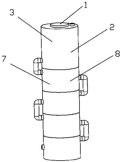
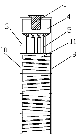
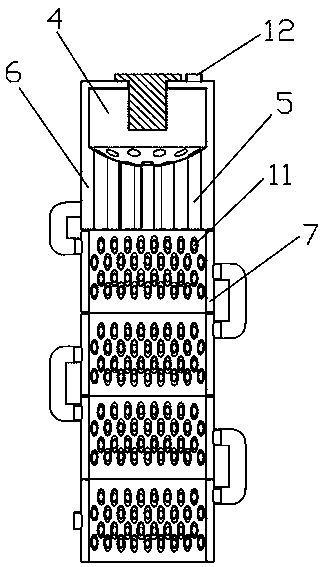
[0030] For specific implementation: see Figure 1 to Figure 3 , a fully premixed condensing boiler, including a burner 1 and a heat exchanger 2, the heat exchanger 2 includes a heat exchanger shell 3, and a burner installation block is arranged inside the heat exchanger shell 3, and the combustion There is a combustion chamber 4 inside the installation block of the burner. The raw smoke end of the burner is arranged in the combustion chamber and generates high-temperature flue gas. A number of heat exchange tubes 5 are connected between the bottom of the installation block of the burner and the inner bottom surface of the heat exchanger shell. The heat exchange chamber 6 is formed by the gap between the heat exchange tube, the burner installation block and the inside of the heat exchanger shell. A condenser 7 is provided at the bottom of the heat exchanger sh...


PUM


Abstract

The invention discloses a full-premixing condensation boiler. The boiler comprises a combustor and a heat exchanger, the heat exchanger comprises a heat exchanger shell, a combustor mounting block isarranged in the heat exchanger shell, a combustion chamber is formed in the combustor mounting block, a plurality of heat exchange tubes are arranged between the bottom of the combustor mounting blockand the inner bottom surface of the heat exchanger shell in a connection mode, a heat exchange chamber is formed by the heat exchange tubes and a gap between the combustor mounting block and the interior of the heat exchanger shell, a condenser is arranged at the bottom of the heat exchanger shell, the condenser comprises a cylinder body, the cylinder body penetrates up and down to form a condensation channel, one end of each heat exchange tube communicates with the combustion chamber in the combustor mounting block, and the other end communicates with the condensation channel, a water inletcavity and a water outlet cavity are formed in an interlayer between the outer side wall of the cylinder body and the inner side wall formed by the condensation channel, a plurality of condensation pipes transversely arranged in the condensation channel are arranged between the water inlet cavity and the water outlet cavity in a connection mode, and the two ends of each condensation pipe communicate with the water inlet cavity and the water outlet cavity respectively. The boiler can greatly improve the heat efficiency.

Description

technical field [0001] The invention belongs to boiler equipment, in particular to a fully premixed condensing boiler. Background technique [0002] Fully premixed condensing boiler is a new type of hot water boiler that integrates the two most energy-saving technologies at present—full premixed technology and condensing technology. Full premixed is to fully mix gas and air in a certain proportion before combustion. In the combustion process, the combustion method of supplying air is no longer required. The fully premixed combustion flame spreads quickly, the volumetric heat intensity of the combustion chamber is high, and complete combustion can be achieved with a small excess air coefficient, which can generate very high temperature. High temperature flue gas. [0003] A general fully premixed condensing boiler includes a burner and a heat exchanger. The smoke end of the burner is installed in the combustion chamber of the heat exchanger. Straight heat exchange tubes are...

Claims


Application Information

Patent Timeline
IPC IPC(8): F24H1/28F24H8/00F24H9/00F24H9/12F24H9/14F24H9/18
CPCF24H1/282F24H8/00F24H9/1836F24H9/146F24H9/0005F24H9/13Y02B30/00
Inventor 王大明
Owner 喀什翰明燃气设备有限公司
Learn More