MEMS micromirror scanning light path system

A technology of optical path system and micromirror, which is applied in the field of scanning micromirror, can solve the problems of small picture, small scanning angle of MEMS imaging, and large space occupied by projection, and achieve the effect of small power, large scanning angle, and no need for heat dissipation

Inactive Publication Date: 2020-04-24
西安慧炬云创电子科技有限公司
View PDF4 Cites 0 Cited by
  • Summary
  • Abstract
  • Description
  • Claims
  • Application Information

AI Technical Summary

Problems solved by technology

[0004] The optical path invention of this optical design solves the problem of small scanning ang

Method used


Image

  • MEMS micromirror scanning light path system
  • MEMS micromirror scanning light path system

Examples


Example Embodiment

[0015] In order to further illustrate the technical means and effects adopted by the present invention to achieve the predetermined purpose, the specific embodiments, structural features and effects of the present invention will be described in detail below with reference to the accompanying drawings and examples.
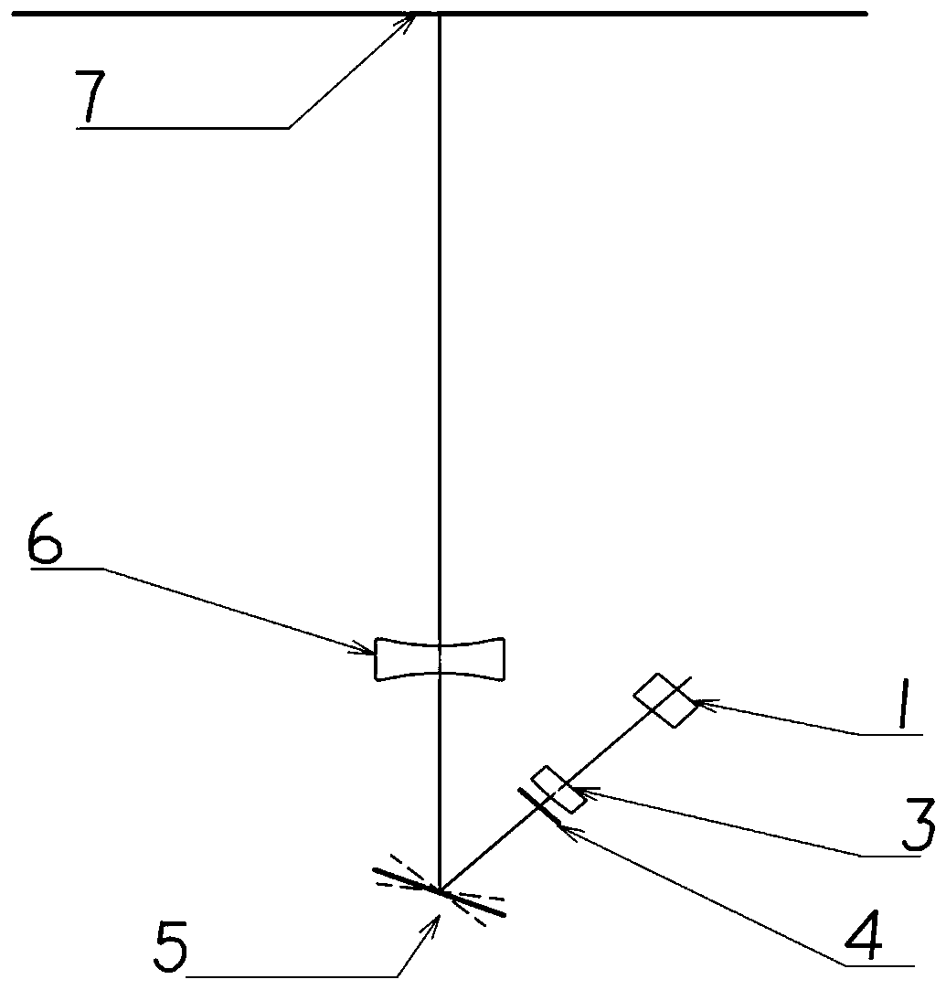
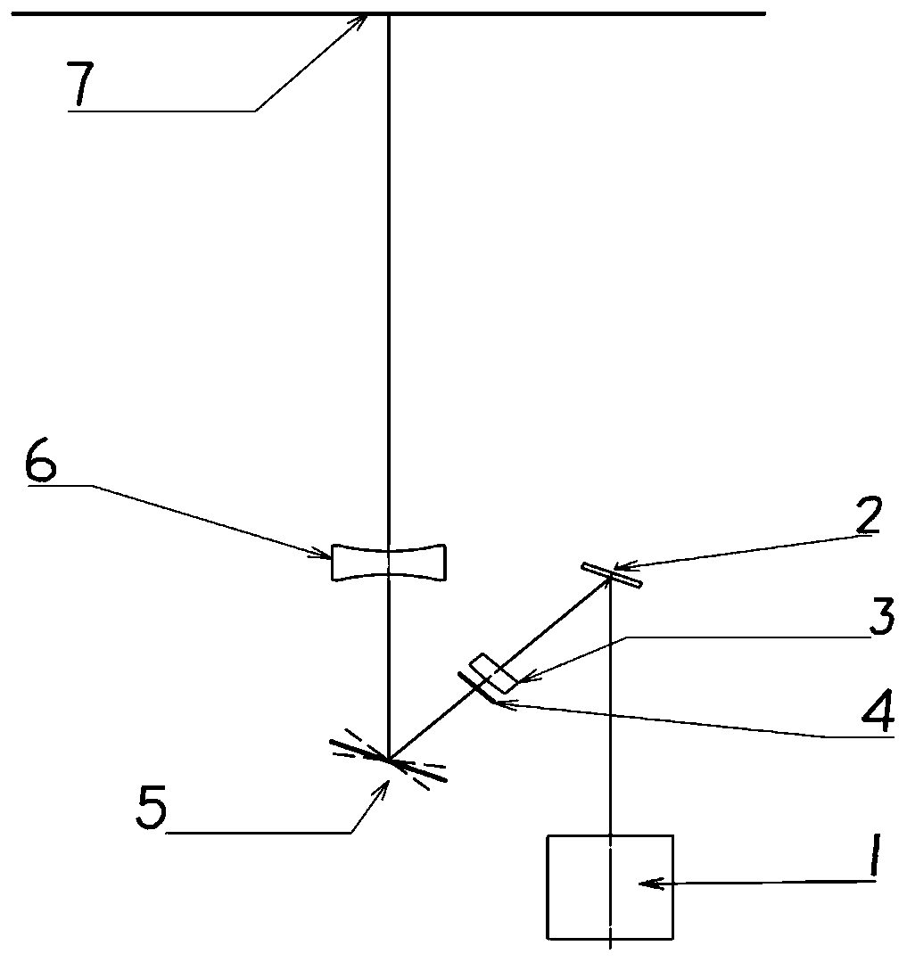
[0016] A MEMS micro-mirror scanning optical path system includes: a laser 1, a compensation lens 3, an aperture 4, a MEMS micro-mirror 5, a beam expander lens 6 and an imaging screen 7; the light generated by the laser 1 passes through the compensation lens 3, the light The aperture 4, the MEMS micromirror 5 and the beam expander lens 6 are displayed on the imaging screen.

[0017] The laser 1 and the compensation lens 3 can communicate with the optical path through the incident mirror 2.

[0018] The aperture of the aperture 4 is matched with the size of the scanning lens of the MEMS micromirror 5 to avoid diffraction fringes on the comb-tooth microstructure on the edge ...


PUM


Abstract

The invention belongs to the technical field of scanning micromirrors, and particularly relates to an MEMS micromirror scanning light path system. The MEMS micromirror scanning light path system comprises a laser, a compensation lens, a diaphragm small hole, an MEMS micromirror, a beam expanding lens and an imaging screen. Light rays generated by the laser sequentially pass through the compensation lens, the diaphragm small hole, the MEMS micromirror and the beam expanding lens and then are displayed on the imaging screen. The scheme has the characteristics that the projection distance is adjustable and clear imaging can be realized at different distances, the whole optical system is large in scanning angle and large in image picture, and the imaging of a large picture can be realized witha small volume.

Description

technical field [0001] The invention belongs to the technical field of scanning micromirrors, and in particular relates to a MEMS micromirror scanning optical path system. Background technique [0002] In the existing technical solutions, the MEMS micromirror directly scans the majority. Due to the limitation of the overall design and processing technology of the MEMS micromirror, the current scanning angle is generally at a maximum of ±6°, and the scanning picture is small. To obtain a larger picture, it must be achieved by increasing the projection distance. , making the overall volume larger. In addition, if the scanning angle of the MEMS micromirror is too large, the linearity of the driving voltage will be poor, the scanning repetition stability will be poor, and the image will shake seriously. Contents of the invention [0003] In order to solve the above-mentioned problems in the prior art, the present invention provides a MEMS micromirror scanning optical path sys...

Claims


Application Information

Patent Timeline
IPC IPC(8): G02B26/08G02B27/09
CPCG02B26/0833G02B27/0955
Inventor 王琅
Owner 西安慧炬云创电子科技有限公司
Why Eureka
Try Eureka