Eureka AIR delivers breakthrough ideas for toughest innovation challenges, trusted by R&D personnel around the world.

Polishing machine tool for machining metal plates

A metal sheet and machine tool technology, applied in the field of grinding machine tools for sheet metal processing, can solve the problems of inadvertent and ideal grinding efficiency, single movement mode, etc., and achieve the effect of ensuring tight fit, facilitating tight fit and improving grinding effect.

Active Publication Date: 2020-04-28
徐州亦维制造有限公司
View PDF8 Cites 2 Cited by
  • Summary
  • Abstract
  • Description
  • Claims
  • Application Information

AI Technical Summary

Problems solved by technology

[0003] The executive part of the grinding machine is generally a grinding disc. The grinding disc in the existing grinding machine can only rotate around the axis when it is working, and the movement mode is relatively simple, so the grinding efficiency is ideal.

Method used


Image

  • Polishing machine tool for machining metal plates
  • Polishing machine tool for machining metal plates
  • Polishing machine tool for machining metal plates

Examples


Embodiment 1

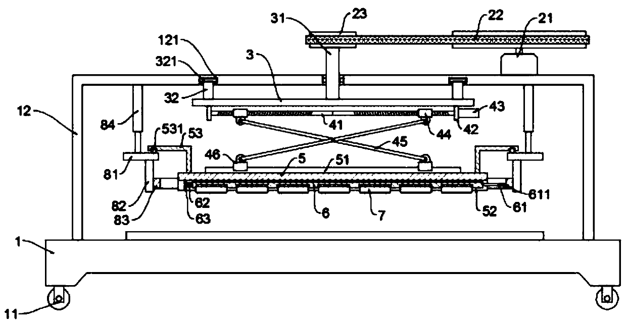
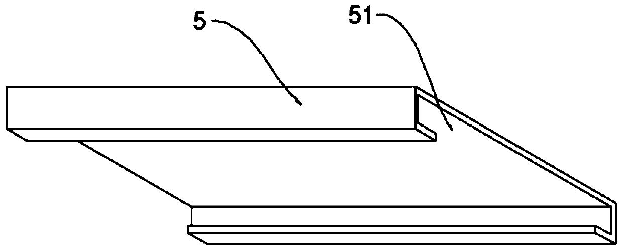
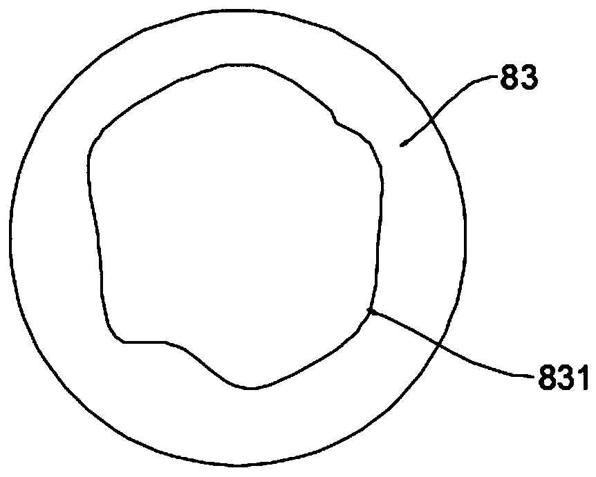
[0024] see Figure 1~4 , in an embodiment of the present invention, a grinding machine tool for sheet metal processing, comprising a bed body 1, a rotating seat 3, a mounting seat 5 and a connecting seat 6; Located below the gantry 12 and rotatably connected with the gantry 12 through the rotating shaft 31, the gantry 12 is provided with a driving mechanism for driving the rotating shaft 31; the mounting seat 5 is connected with the rotating seat 3 through a lifting mechanism, and the mounting seat 5 Both sides of the top are symmetrically fixed with a collision plate 53, the collision plate 53 is L-shaped and the balls 531 that are movable are embedded on the horizontal plate body; Corresponding to the elastic connector 84, the end of the elastic connector 84 is fixed with a horizontal plate 81, the horizontal plate 81 is located below the horizontal plate body of the collision plate 53 and conflicts with the ball 531, the bottom of the horizontal plate 81 is fixed with a ver...

Embodiment 2

[0034] see Figure 5 , the embodiment of the present invention is optimized on the basis of embodiment 1, mainly for the improvement of the grinding parts, specifically:

[0035]In this embodiment, the grinding member includes a plurality of grinding units 7 evenly distributed on the bottom of the connecting base 6, and the connecting base 6 is provided with mounting grooves 54 corresponding to the grinding units 7 one by one. It is connected with the installation groove 54, so that it can be adaptively stretched according to the outer surface of the workpiece, so as to ensure the close fit between the grinding unit 7 and the workpiece. At the same time, a plurality of grinding units 7 are provided, and the expansion and contraction between adjacent grinding units 7 will not be mutual. The impact is more conducive to its close fit with the workpiece.


PUM


Abstract

The invention discloses a polishing machine tool for machining metal plates. The polishing machine tool comprises a machine tool body, a rotating seat, a mounting seat and a connecting seat; the mounting seat is provided with a clamping groove, the connecting seat is slidably clamped in the clamping groove, and a polishing member is arranged at the bottom of the connecting seat; and one end of theconnecting seat is connected with a fixed plate fixed at the clamping groove through a return spring, and a rotating rod is fixed at the other end of the connecting seat. According to the polishing machine tool for machining metal plates, due to the fact that the connecting seat is sliably arranged in the mounting seat, in combination with the arrangement of abutting rods, elastic telescopic pieces, transverse plates, vertical plates, fixed rings and the rotating rod, the connecting seat can move on the horizontal plane while rotating around the axis, and accordingly the polishing effect of the polishing member on a workpiece is improved.

Description

technical field [0001] The invention relates to the field of machine tool processing, in particular to a grinding machine tool for metal plate processing. Background technique [0002] Machine tools refer to machines that manufacture machines. There are many ways to process mechanical parts in modern machinery manufacturing: in addition to cutting, there are also casting, forging, welding, stamping, extrusion, etc., but all of them have higher precision requirements and higher surface roughness requirements. Fine parts generally need to be final processed by cutting on the machine tool, and the grinding machine tool is a very common machine tool, and its function is to grind the outer surface of the workpiece. [0003] The executive part of the grinding machine tool is generally a grinding disc. The grinding disc in the existing grinding machine tool can only rotate around the axis when it is working, and the movement mode is relatively simple, so the grinding efficiency is ...

Claims


Application Information

Patent Timeline
IPC IPC(8): B24B7/07B24B27/00B24B41/02B24B47/12B24B47/22B24B41/04B24B41/00
CPCB24B7/07B24B27/0007B24B41/007B24B41/02B24B41/04B24B47/12B24B47/22
Inventor 朱骏
Owner 徐州亦维制造有限公司
Why Eureka
Eureka Blog
Learn More