
Floor tile cutting device and cutting method

A cutting device, a technology for floor tiles, applied in stone processing tools, work accessories, manufacturing tools, etc., can solve the problems of low cutting precision, inconvenient operation, low cutting efficiency, etc., and achieve high cutting precision, simple and convenient use, and improved The effect of cutting efficiency

Active Publication Date: 2020-04-28
BOZHOU VOCATIONAL & TECHNICAL COLLEGE
View PDF6 Cites 3 Cited by
  • Summary
  • Abstract
  • Description
  • Claims
  • Application Information

AI Technical Summary

Problems solved by technology

[0006] Aiming at the problems of low cutting precision in oblique cutting and inconvenient operation and low cutting efficiency caused by multiple positioning of floor tiles in the prior art, the present invention provides a floor tile cutting device and a cutting method thereof; The floor tiles need to be positioned once. Without changing the placement of the floor tiles, it is possible to perform oblique cutting at any angle on the floor tiles for many times. The cutting accuracy is high, the operation is simple and convenient, and the cutting efficiency is high.

Method used


Image

  • Floor tile cutting device and cutting method
  • Floor tile cutting device and cutting method
  • Floor tile cutting device and cutting method

Examples


Embodiment 1

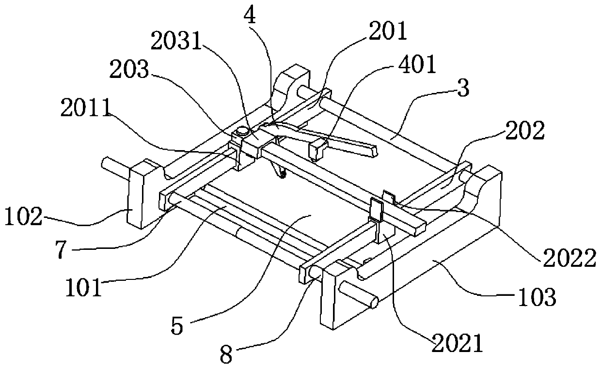
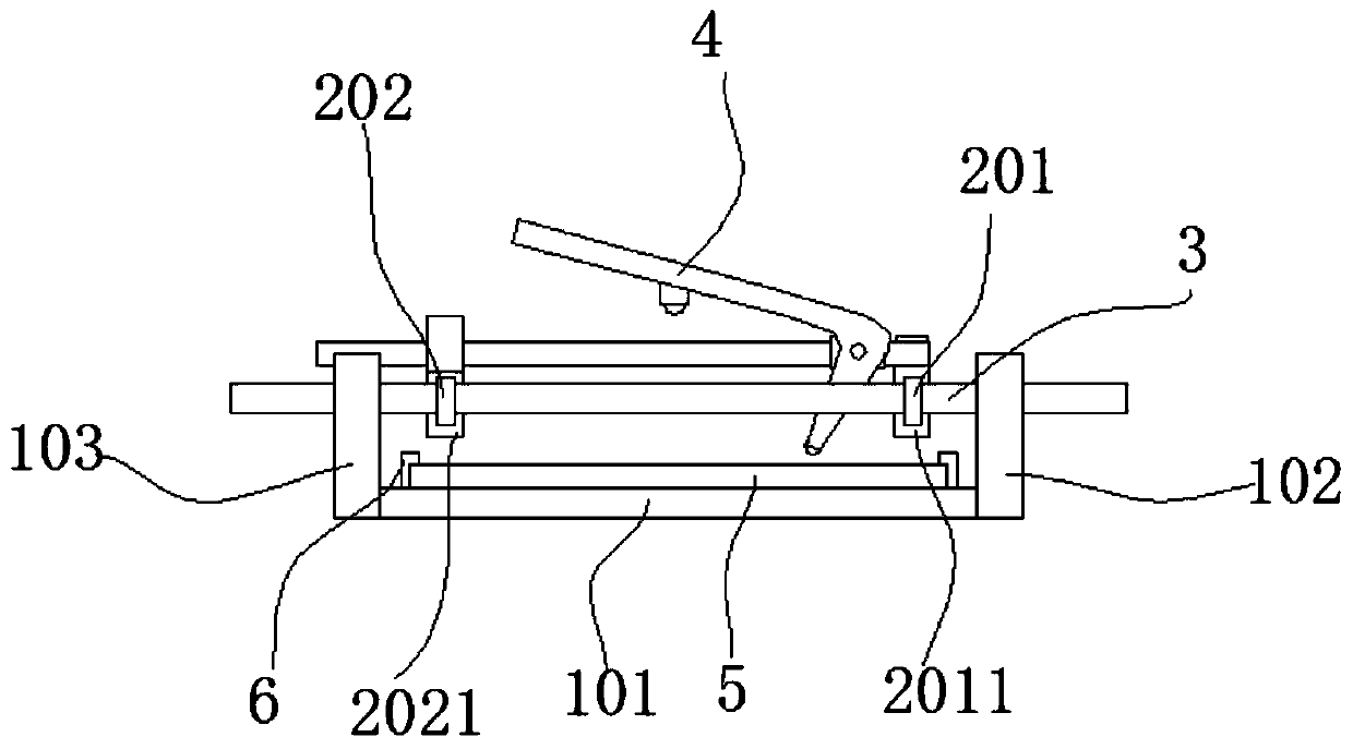
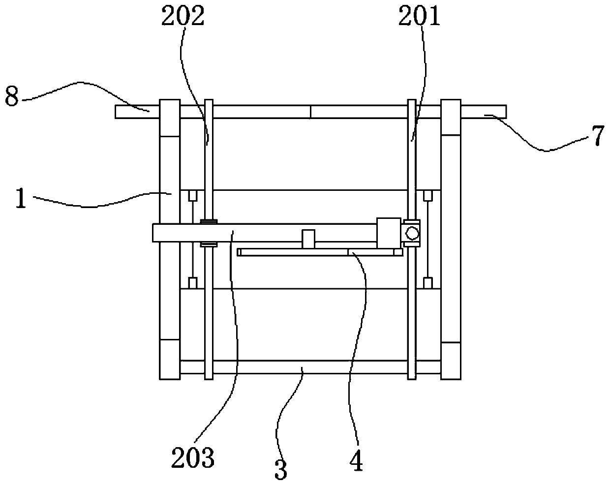
[0045] A floor tile cutting device, comprising a support base 1, an adjustment mechanism 2 and a cutting mechanism 4, the support base 1 includes a base 101, a right bracket 102 and a left bracket 103; the right bracket 102 and the left bracket 103 are connected to the base 101 opposite ends; the cutting mechanism 4 is located between the right bracket 102 and the left bracket 103; the adjustment mechanism 2 includes a second rail 202 and a third rail 203; one end of the third rail 203 is hinged On the right bracket 102, the other end can rotate around the hinge point at the level of the third track 203; the cutting mechanism 4 is slidably connected to the third track 203; the second track 202 is used to fix the second track 203 The movable ends of the three rails 203; the second rail 202 can move in the space between the right bracket 102 and the left bracket 103.

[0046] Specifically, a guide rod 3 is connected between the right bracket 102 and the left bracket 103 ; the se...

Embodiment 2

[0053] With embodiment 1, difference is: as Figure 1 to Figure 3 , Figure 5 and Figure 6 As shown, the adjustment mechanism 2 also includes a first track 201; the first track 201 is arranged parallel to the second track 202; the first track 201 is slidably connected to the guide rod 3, and the first track 201 is The hinge ends of the three rails 203 are hinged on the first rail 201 .

[0054] Specifically, the first rail 201 is slidably connected with the first slider 2011 ; the hinge end of the third rail 203 is hinged on the upper surface of the first slider 2011 .

[0055] In this embodiment, the third rail 203 is hinged on the first slider 2011 that is slidably connected to the first rail 201, so that the third rail 203 can be rotated at any angle (less than 90°), and the second rail 202 can The movable end of the third rail 203 is fixed, so that the cutting mechanism 4 can perform oblique cutting at any angle along the third rail 203 . Of course, there is damping b...

Embodiment 3

[0057] A kind of floor tile cutting method, use the floor tile cutting device described in embodiment 2, it is specifically described below:

[0058] A kind of floor tile cutting method, its specific steps are:

[0059] a. place the floor 5 to be cut on the base 101, and fix the floor 5 with the fixing mechanism 6;

[0060] b. Turn the first screw mandrel 7 to adjust the position of the first track 201, move the first slider 2011, rotate the third track 203 around the hinge point, rotate the second screw mandrel 8, and adjust the position of the second track 202, Move the second slider 2021, rotate the fixed splint 2022, so that the fixed splint 2022 fixes the movable end of the third track 203;

[0061] c. Pull the handle, pull the knife holder to rotate, the cutter 402 cuts into the floor 5, and at the same time, the limit unit 401 is pressed against the third rail 203;

[0062] d. The third slider 2031 moves along the length direction of the third track 203 , and the cutt...


PUM


Abstract

The invention discloses a floor tile cutting device and cutting method, and belongs to the technical field of floor tile cutting. The floor tile cutting device comprises a supporting seat, a cutting mechanism and an adjusting mechanism; the supporting seat comprises a base, a right support and a left support, the right support and the left support are connected to the two opposite ends of the base, and the cutting mechanism is located between the right support and the left support; the adjusting mechanism comprises a second rail and a third rail, one end of the third rail is hinged to the right support, the other end of the third rail can rotate around the hinged point, and the cutting mechanism is slidably connected to the third rail; and the second rail is used for fixing the movable endof the third rail, the second rail can move in a space between the right support and the left support. According to the floor tile cutting device and cutting method, a floor tile only needs to be positioned once, on the premise of not changing the placing position of the floor tile, oblique cutting at any angle can be carried out on the floor tile for multiple times, the cutting precision is high, use is easy and convenient, popularization is facilitated, the cutting efficiency is also improved, and the floor tile cutting device has the advantages of being simple in structure, reasonable in design and easy to manufacture.

Description

technical field [0001] The invention belongs to the technical field of floor tile cutting, and in particular relates to a floor tile cutting device and a cutting method thereof. Background technique [0002] Floor tiles are widely used, and it is usually necessary to cut the floor tiles when laying them. In the prior art, the cutting of the floor tiles is all cutting perpendicular to the edge of the floor tiles, that is, vertical cutting; however, when laying floor tiles in art, the floor tiles need to be cut obliquely, that is, the cutting path is usually not perpendicular to the edge of the floor tiles. Therefore, it is of great significance to design a floor tile cutting machine that can realize an oblique cutting path in any direction. [0003] For this reason, the Chinese patent number is 2018107155887, and the Chinese patent technical document published on November 27, 2018 provides a universal floor tile cutting machine, which includes a left bracket installed on the...

Claims


Application Information

Patent Timeline
Patent Type & Authority Applications(China)
IPC IPC(8): B28D1/22B28D7/00
CPCB28D1/228B28D7/00
Inventor 刘珍徐婧朱钧
Owner BOZHOU VOCATIONAL & TECHNICAL COLLEGE
Learn More