
Inked ribbon coding machine

A coding machine and ribbon technology, applied in printing devices, printing, inking devices, etc., can solve problems such as too thick font printing, low coding quality, and easy adhesion of ribbons, so as to improve printing quality and increase printing efficiency. The effect of high code quality and easy secondary use

Inactive Publication Date: 2020-04-28
杨俊玲
View PDF3 Cites 0 Cited by
  • Summary
  • Abstract
  • Description
  • Claims
  • Application Information

AI Technical Summary

Problems solved by technology

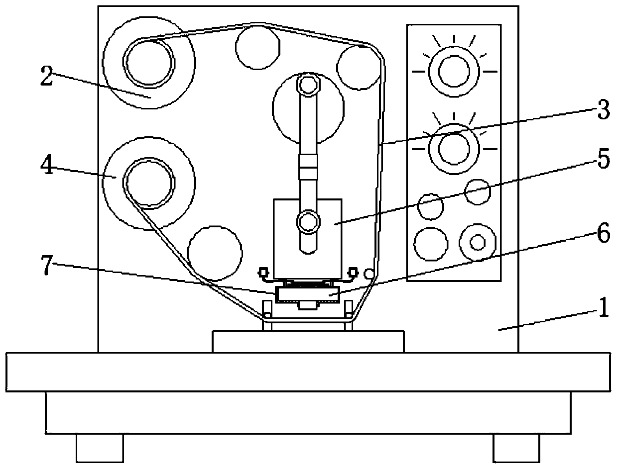
[0003] The existing ribbon coding machine consists of a ribbon unwinding mechanism, a ribbon take-up mechanism, a drive mechanism and a print head. The working principle of the ribbon coding machine is that the ribbon is installed on the ribbon unwinding mechanism, and then the ribbon passes through the Assemble, pull the ribbon to the bottom of the print head, then connect the stretched end of the ribbon to the take-up mechanism, then place the substrate on the bottom of the print head, the heating device inside the print head gradually heats the print head, and then The driving mechanism drives the print head to reciprocate downward. Since the print head has a certain temperature, every time it contacts the ribbon, the ink on the ribbon is melted and printed on the substrate. The temperature control device of the existing print head It is mainly composed of a temperature sensor and a controller. The user sets the temperature range, and then the print head does not rise after rising to this temperature. With the long-term use of the print head, and the instructions of the sensor and the controller are more complicated, the sensor The accuracy of the controller and the accuracy of the controller often fail, causing the temperature of the heating device inside the print head to rise continuously, causing the temperature of the print head to gradually exceed the temperature that the ribbon can withstand, resulting in serious liquefaction of the ink on the ribbon, printing When it is applied to the substrate, it is easy to appear blurred font printing and too thick font printing, and the temperature will melt the surface layer of the ribbon, resulting in burrs on the ribbon, and the ribbon is easy to adhere to the print head, affecting the normal recycling of the ribbon , in severe cases, the ribbon will break when heated, which will affect the normal use of the ribbon on the one hand, causing the ribbon to be unable to be used again, and on the other hand, affect the normal coding of the substrate, resulting in lower quality of coding

Method used


Image

  • Inked ribbon coding machine
  • Inked ribbon coding machine
  • Inked ribbon coding machine

Examples


Embodiment Construction

[0017] The following will clearly and completely describe the technical solutions in the embodiments of the present invention with reference to the accompanying drawings in the embodiments of the present invention. Obviously, the described embodiments are only some, not all, embodiments of the present invention. Based on the embodiments of the present invention, all other embodiments obtained by persons of ordinary skill in the art without making creative efforts belong to the protection scope of the present invention.

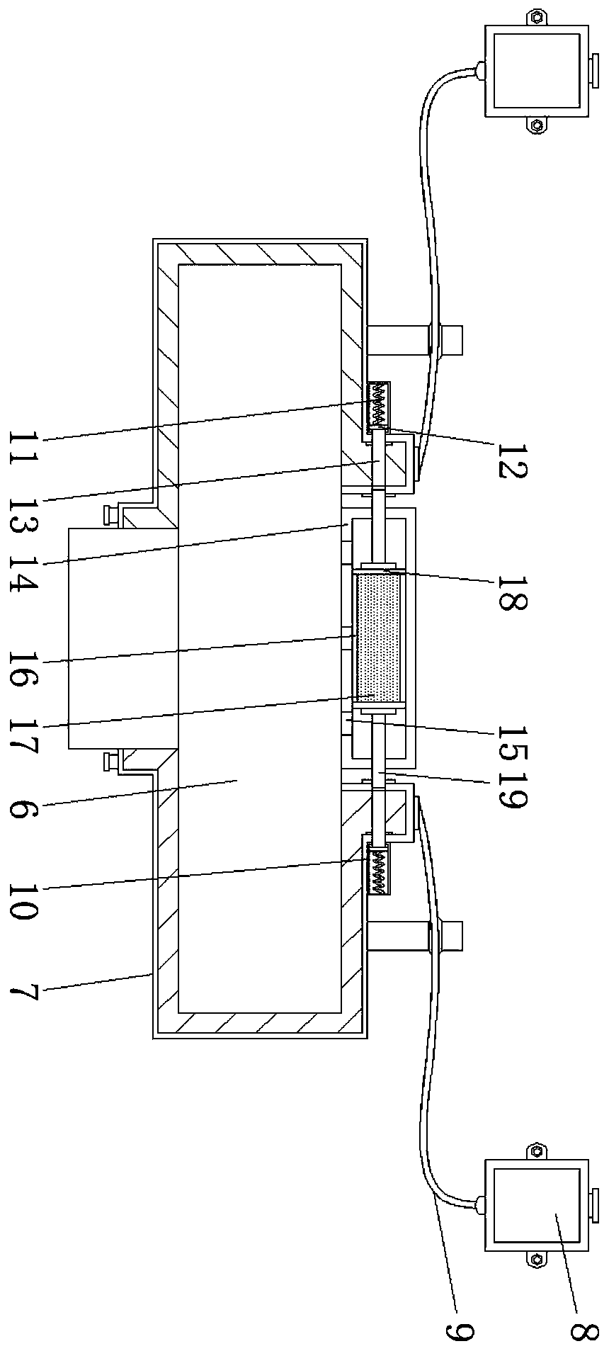
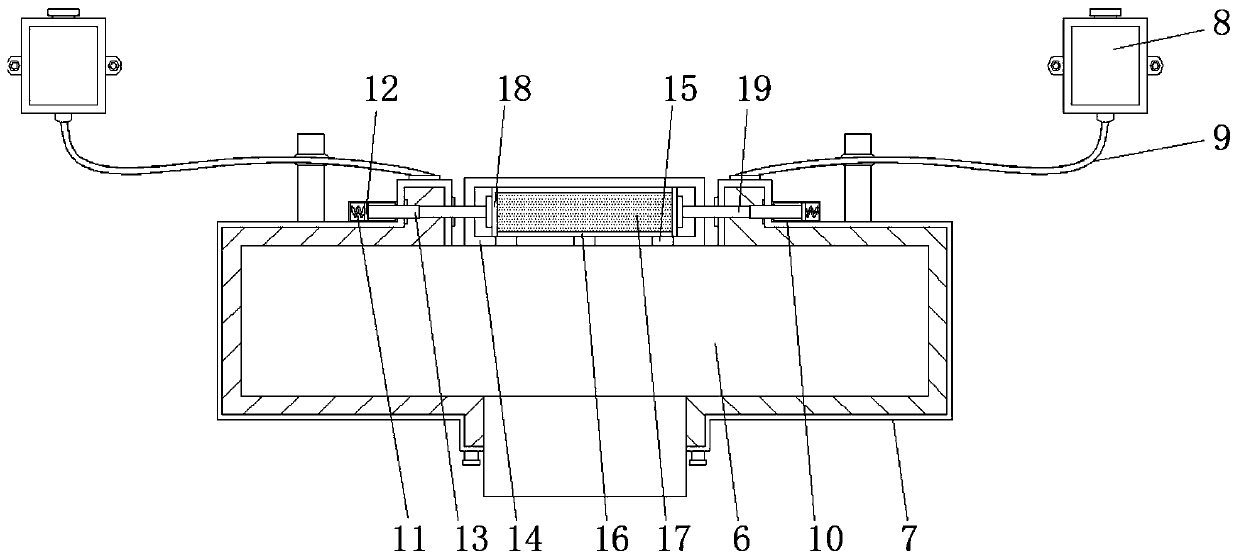
[0018] see Figure 1-3 , a color ribbon coding machine, including a body 1, a tape unwinding mechanism 2, a ribbon 3, a take-up mechanism 4, a driving device 5, a print head 6, the ribbon unwinding mechanism 2 is arranged on the side of the body 1, and the ribbon 3 rolls Connected to the tape unwinding mechanism 2, the tape take-up mechanism 4 is arranged at the end of the ribbon 3 and fixedly connected to the side of the body 1, the driving device 5 is arrang...


PUM


Abstract

The invention relates to the technical field of printing equipment and discloses an inked ribbon coding machine. The inked ribbon coding machine comprises a machine body, a ribbon unwinding mechanism,an inked ribbon, a ribbon winding mechanism, a driving device and a printing head. The ribbon unwinding mechanism is arranged on the side face of the machine body. The inked ribbon is connected to the ribbon unwinding mechanism. The ribbon winding mechanism is arranged at the tail end of the inked ribbon and fixedly connected with the side face of the machine body. The driving device is arrangedon the middle portion of the machine body. The printing head is mounted at the tail end of the driving device. A cooling pipe is arranged outside the printing head. Through direct cooperation of a water storage tank and a hose, cooling fluid can be directly filled into the cooling pipe, so that the cooling fluid and the cooling pipe are wrapped on the outer portion of the printing head to quicklycool the printing head, and the printing head remains the proper temperature to carry out processing on the inked ribbon. On the one hand, the coding quality is improved; and on the other hand, damageto the inked ribbon is reduced, and secondary application of the inked ribbon is facilitated. Through the design of heat expansion and cold contraction of a soft jacket and thermosensitive liquid, the thermosensitive liquid can achieve the self-adaptive expansion and contraction effect according to the real-time temperature of the printing head.

Description

technical field [0001] The invention relates to the technical field of printing equipment, in particular to a color ribbon coding machine. Background technique [0002] Ribbon coding machine is a kind of coding machine, which uses thermal printing tape instead of ink printing, and adopts a special movable type loading and unloading structure, which can be used to code on any flexible packaging materials. The printing is clear and not easy to erase. [0003] The existing ribbon coding machine consists of a ribbon unwinding mechanism, a ribbon take-up mechanism, a drive mechanism and a print head. The working principle of the ribbon coding machine is that the ribbon is installed on the ribbon unwinding mechanism, and then the ribbon passes through the Assemble, pull the ribbon to the bottom of the print head, then connect the stretched end of the ribbon to the take-up mechanism, then place the substrate on the bottom of the print head, the heating device inside the print head...

Claims


Application Information

Patent Timeline
Patent Type & Authority Applications(China)
IPC IPC(8): B41J33/14B41J33/02B41J2/325B41J29/377
CPCB41J2/325B41J29/377B41J33/02B41J33/14
Inventor 杨俊玲
Owner 杨俊玲
Learn More