Thread shearing or presser foot lifting drive mechanism of sewing machine and thread shearing or presser foot lifting device

A technology of thread trimming mechanism and driving mechanism, which is applied in the field of sewing machines, can solve the problems that the electromagnet electromagnet stroke cannot be changed flexibly, affecting the stable operation of the sewing machine, large shaking and noise, etc., so as to reduce the risk of oil leakage, occupy a small space, reduce The effect of the driving source

Pending Publication Date: 2020-04-28
台州市福崎缝纫机有限公司
View PDF0 Cites 6 Cited by
  • Summary
  • Abstract
  • Description
  • Claims
  • Application Information

AI Technical Summary

Problems solved by technology

However, the electromagnet as the driving source has the disadvantage that the electromagnet stroke cannot be flexibly changed, and it will produce large shaking and noise during movement, resulting in high noise of the sewing machine and affecting the stable operation of the sewing machine, so it is gradually eliminated.
The prior art has also designed a variety of models driven by motors, combined with cams and crank mechanisms, to design rotation track track grooves on the cams to realize thread trimming or presser foot lifting actions. However, in the design scheme using cams and crank mechanisms, Due to the influence of the torque arm transformation of the cam and crank on the motor output shaft, the load on the rotation process is greatly increased, which may easily cause the motor to be stuck and damaged, thereby affecting production work

Method used


Image

  • Thread shearing or presser foot lifting drive mechanism of sewing machine and thread shearing or presser foot lifting device
  • Thread shearing or presser foot lifting drive mechanism of sewing machine and thread shearing or presser foot lifting device
  • Thread shearing or presser foot lifting drive mechanism of sewing machine and thread shearing or presser foot lifting device

Examples


specific Embodiment

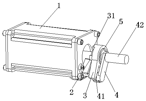
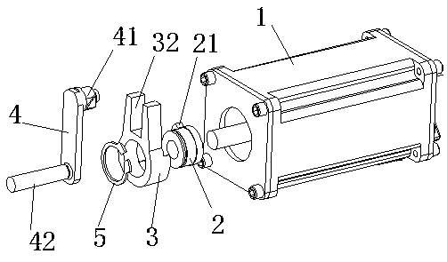
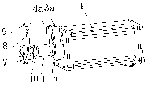
[0026] refer to Figure 1-7, the present invention is a specific embodiment for improving the cam or crank drive assembly driven by electromagnets and motors in the prior art: a thread trimming or presser foot driving mechanism of a sewing machine, including a motor 1, and the action of the motor 1 Controlled by the control box, it is used to drive the clutch drive assembly for thread trimming or presser foot lifting action. When it is used to dock the thread trimming mechanism and the motor shaft, it is set as the thread trimming clutch drive assembly, which is set as Embodiment 1; it is used for docking and lifting. The presser foot mechanism and the motor shaft are the presser foot lifter clutch drive assembly, which is set to embodiment 2; specifically, the thread trimmer or presser foot lifter clutch drive assembly includes a clutch mandrel 2, a clutch shift fork 3 and a drive crank 4, wherein The clutch mandrel 2 is arranged on the motor shaft of the motor 1, and a raise...


PUM


Abstract

The invention discloses a thread shearing or presser foot lifting drive mechanism of a sewing machine. The drive mechanism comprises a motor, a clutch mandrel, a clutch yoke and a drive crank. A motordrive mode replaces a high-power electromagnet, the clutch mandrel with a short force arm is adopted and the clutch yoke is driven to rotate by output of a motor shaft, so that the effect of the large torque on the motor shaft due to a long moment arm of a cam or the crank is reduced, and the overall transmission stability and reliability are high. In addition, the invention discloses a thread shearing or presser foot lifting device. The actions of a thread shearing mechanism and a presser foot lifting mechanism are controlled through a double-end motor, and compared with the prior art, drivesources are reduced, the structure is simpler, the occupied space is small, installation is convenient, and the cost is reduced; moreover, compared with an electromagnet, motor drive has the advantages that the noise is reduced; and further, by combination with an anti-vibration pad, the stability of the whole device is improved, and shake and noise are reduced.

Description

technical field [0001] The invention relates to the technical field of sewing machines, in particular to a thread trimming or presser foot lifting driving mechanism of a sewing machine and a thread trimming and presser foot lifting device using the mechanism. Background technique [0002] The thread trimmer driving mechanism and the presser foot lifting mechanism on the sewing machine are generally two mechanisms independent of each other at present. The thread trimming drive mechanism for thread trimming and the presser foot lifter lever for lifting the presser foot are generally driven by two electromagnets respectively. However, the electromagnet as the driving source has the disadvantage that the electromagnet stroke cannot be flexibly changed, and it will generate large shaking and noise during movement, resulting in high noise of the sewing machine and affecting the stable operation of the sewing machine, so it is gradually eliminated. The prior art has also designed ...

Claims


Application Information

Patent Timeline
Patent Type & Authority Applications(China)
IPC IPC(8): D05B65/00D05B29/02D05B69/10
CPCD05B29/02D05B65/00D05B69/10
Inventor 杨辉
Owner 台州市福崎缝纫机有限公司
Why Eureka
Try Eureka