Hardware circuit encryption device realized through CPLD

An encryption device and hardware circuit technology, which is applied in computer security devices, electrical digital data processing, instruments, etc., can solve the problems of complex structure, cost increase, and increase in the size of the main board of the business gateway hardware circuit, and achieve good encryption effect , low cost, good effect

Active Publication Date: 2020-04-28
XINZHONGXIN ELECTRONICS HARBIN
View PDF7 Cites 2 Cited by
  • Summary
  • Abstract
  • Description
  • Claims
  • Application Information

AI Technical Summary

Problems solved by technology

[0003] The purpose of the present invention is to provide a hardware circuit encryption device implemented by CPLD in order to solve the complex structure of the confidential part of the hardware circuit of the business gateway, which leads to the increase in the volume of the mainboard and the increase in cost

Method used


Image

  • Hardware circuit encryption device realized through CPLD
  • Hardware circuit encryption device realized through CPLD
  • Hardware circuit encryption device realized through CPLD

Examples


specific Embodiment approach 1

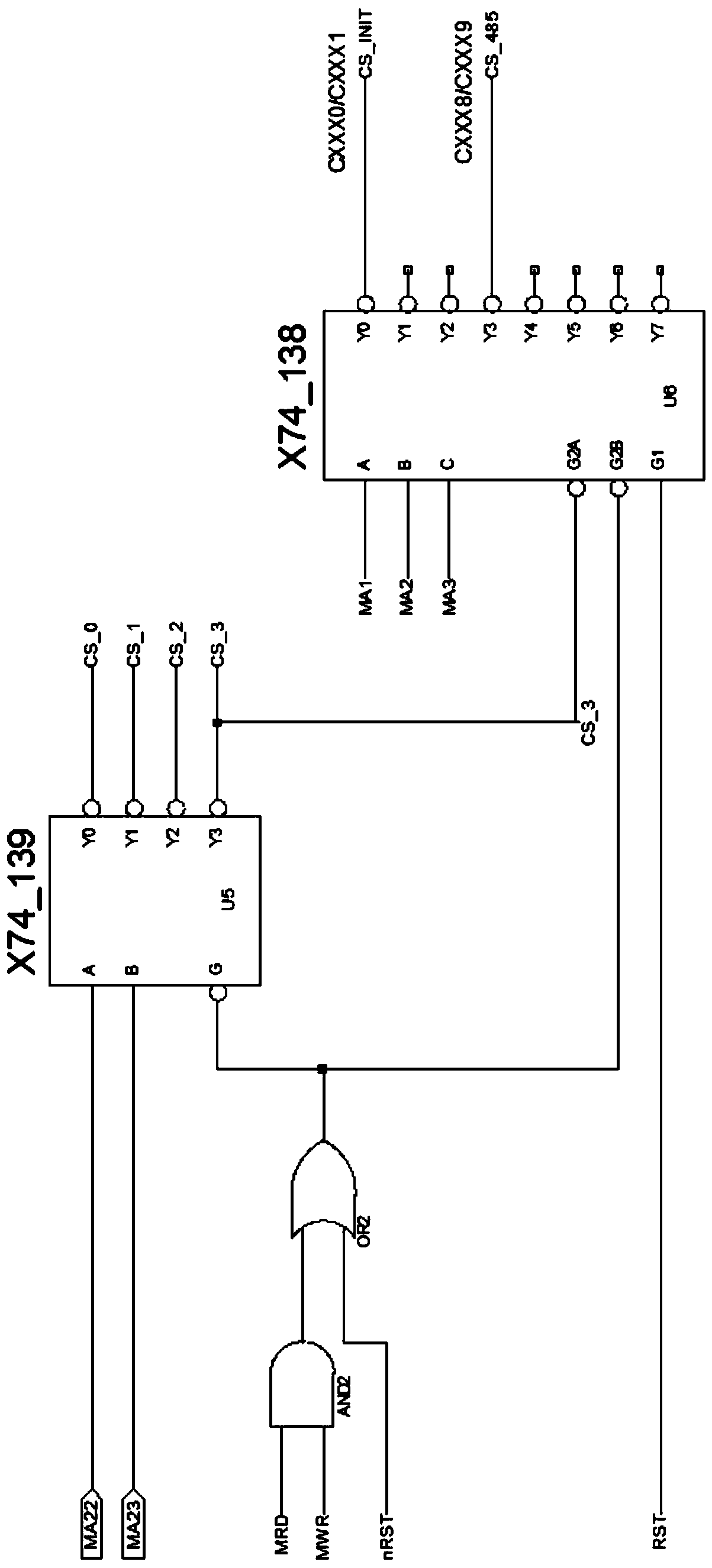
[0018] Specific implementation mode one: combine Figure 1 to Figure 3 This embodiment will be described. The hardware circuit encryption device implemented by CPLD described in this embodiment is suitable for CPLD, and the device includes a decoding module, a password writing module and a communication channel control module.

[0019] Such as figure 1 As shown, the decoding module is a gate circuit decoder realized by a 24 decoder and a 38 decoder, and is used for address decoding of input addresses MA23, MA22, MA3, MA2, MA1; The decoding module specifically includes an AND gate, an OR gate, a 24 decoder and a 38 decoder; the two input terminals of the AND gate are respectively used to receive the read control signal and the write control signal, and the output terminal of the AND gate One input end of the OR gate is connected, the other input end of the OR gate is used to receive the reset signal, and the output end of the OR gate is simultaneously connected with an enable...

specific Embodiment approach 2

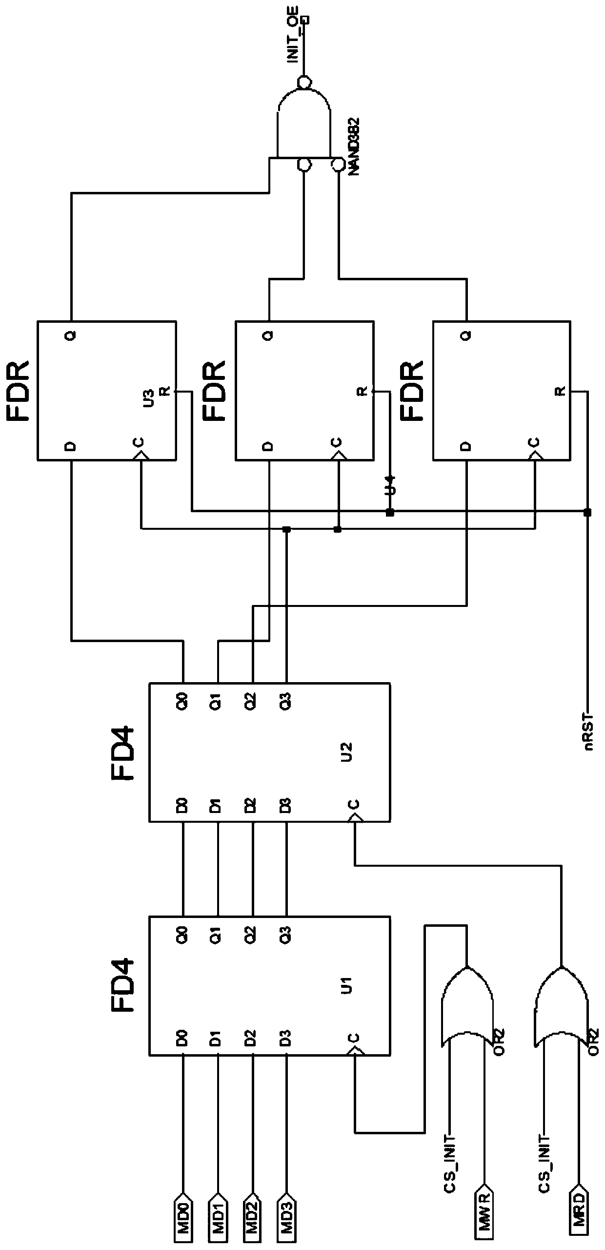
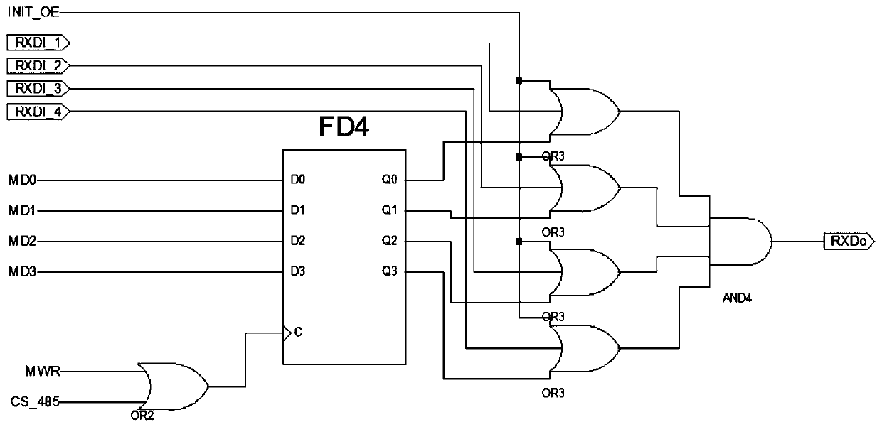
[0028] Specific implementation mode two: combination Figure 1 to Figure 4 This embodiment will be described. In order to realize the confidential control of the internal logic of the CPLD chip so that external programs cannot control the entire product, this embodiment provides an encryption method that cooperates with the above encryption device, and the encryption method is implemented by a computer program embedded in the CPU.

[0029] Such as Figure 4 As shown, the encryption method includes the following steps:

[0030] When the enable signal CS_INIT changes from high level to low level, the preset data 1 goes to IO port MD0, the preset data 0 goes to IO port MD1, the preset data 0 goes to IO port MD2, and the preset data 1 goes to IO port MD2. On the IO port MD3;

[0031] Write data to the occupied address 0CXXX0h or 0CXXX1h;

[0032] Read data from the occupied address 0CXXX0h or 0CXXX1h;

[0033] Preset data 1 to IO port MD0, preset data 0 to IO port MD1, preset...


PUM


Abstract

The invention discloses a hardware circuit encryption device realized through a CPLD (Complex Programmable Logic Device), and aims to solve the problems of increased volume and high cost of a hardwarecircuit mainboard of a business gateway. A decoding module comprises a second-fourth decoder and a third-eighth decoder and is used for carrying out address decoding on an input address; a cryptographic number writing module comprises five D triggers, two OR gates and an NAND gate; the two OR gates are used for receiving a control signal, the output of the two OR gates is used as trigger signalsof the first D trigger and the second D trigger, the output of the first D trigger is used as the input of the second D trigger, and the output of the second D trigger is used as the input of the restthree D triggers; a communication pipeline control module comprises a D trigger, a two-input OR gate, four three-input OR gates and a four-input AND gate, the two-input OR gate is used for receivingcontrol signals, the output of the two-input OR gate serves as the input of the D trigger, the output of the D trigger serves as the input of the three-input OR gate, and the output of the three-inputOR gate serves as the input of the four-input AND gate.

Description

technical field [0001] The present invention relates to the encryption technology of hardware equipment. Background technique [0002] In the application of the one-card business gateway, the hardware circuit of the business gateway is extremely complex, and the main board control requires a large number of logic circuits. The main board of the business gateway adopts a dual-CPU control system. The dual CPUs complete important functions, share storage units and display circuits, and exchange data through public memory, so the control logic is very complicated. In order to complete complex control, it is necessary to design a large number of address decoding circuits, bus switching control circuits, and other encryption protection logic, etc., which not only increases the size of the motherboard, but also increases the cost. Contents of the invention [0003] The object of the present invention is to provide a hardware circuit encryption device realized by CPLD in order to...

Claims


Application Information

Patent Timeline
Patent Type & Authority Applications(China)
IPC IPC(8): G06F21/60
CPCG06F21/602Y02D10/00
Inventor 李英志
Owner XINZHONGXIN ELECTRONICS HARBIN
Why Eureka
Try Eureka