
Method for calculating farthest detection distance of Gm-APD laser radar

A technology of lidar and calculation method, applied in design optimization/simulation, radio wave measurement system, multi-objective optimization, etc., to achieve the effect of power consumption and volume

Active Publication Date: 2020-04-28
HARBIN INST OF TECH
View PDF3 Cites 12 Cited by
  • Summary
  • Abstract
  • Description
  • Claims
  • Application Information

AI Technical Summary

Problems solved by technology

The trigger probability of Gm-APD echo is affected by the echo signal-to-noise ratio and the absolute echo strength. The echo detection probability is affected by the echo signal-to-noise ratio, the absolute echo strength and the number of statistical frames. The traditional linear detection laser Radar theoretical demonstration method cannot effectively demonstrate Gm-APD lidar parameters

Method used


Image

  • Method for calculating farthest detection distance of Gm-APD laser radar
  • Method for calculating farthest detection distance of Gm-APD laser radar
  • Method for calculating farthest detection distance of Gm-APD laser radar

Examples


Embodiment 1

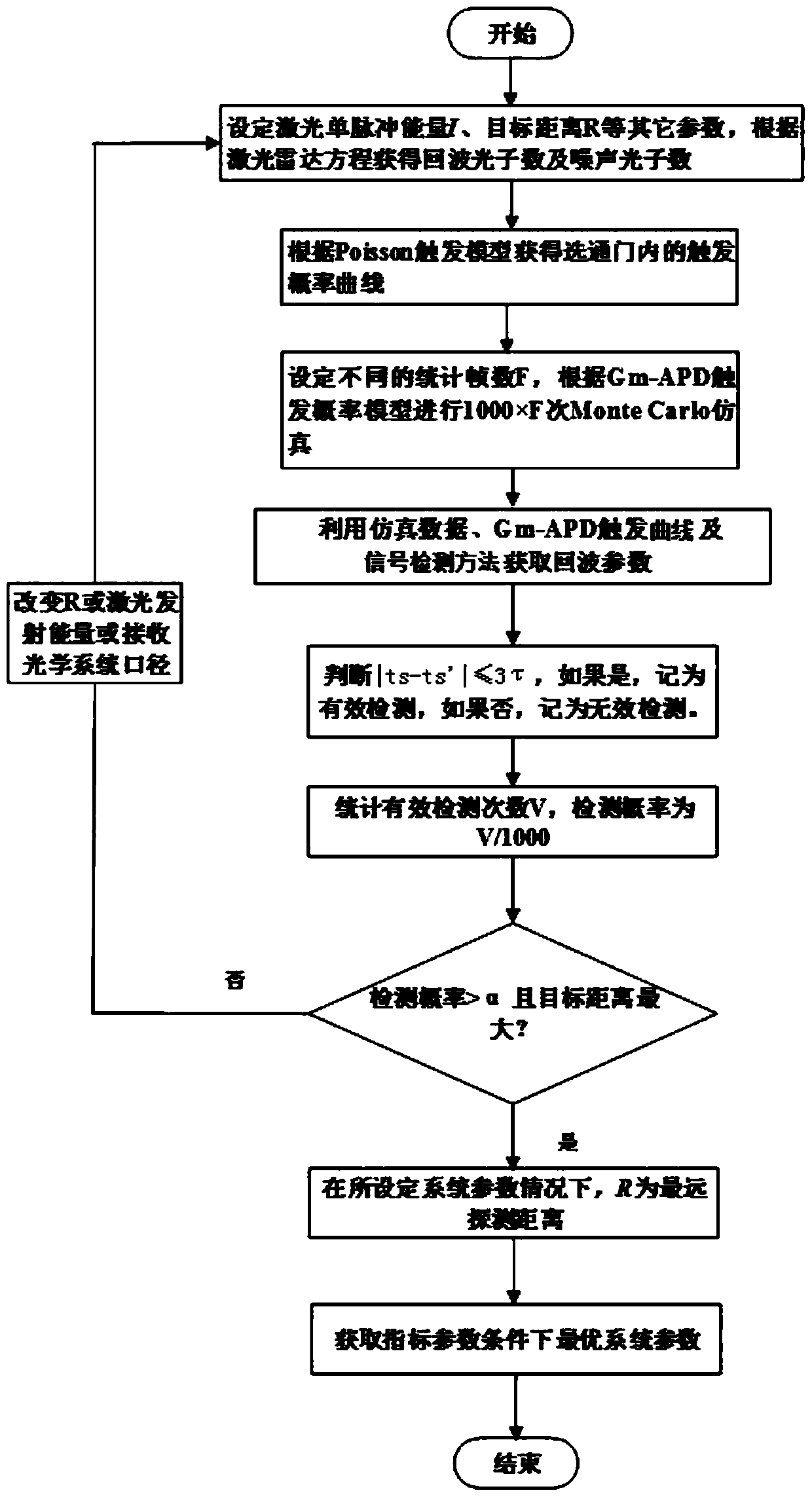
[0044] Such as figure 1 Shown, a kind of calculation method of Gm-APD laser radar farthest detection distance, described calculation method comprises the following steps,

[0045]Step 1: Use the laser radar equation to obtain the echo intensity, set the laser single pulse energy I, the detection distance R and the receiving optical aperture, and obtain the number of echo photons and noise photons according to the laser radar;

[0046] Step 2: Obtain the trigger probability of each time interval of the Gm-APD lidar, and obtain the trigger probability curve in the gate according to the Poisson trigger model;

[0047] Step 3: Use the Monte Carlo method to obtain simulation data under different statistical frame numbers, set different statistical frame numbers F, and perform 1000*F Monte Carlo simulations according to the Gm-APD trigger probability model;

[0048] Step 4: According to the Gm-APD trigger probability curve in step 2 and the simulation data in step 3, use signal det...

Embodiment 2

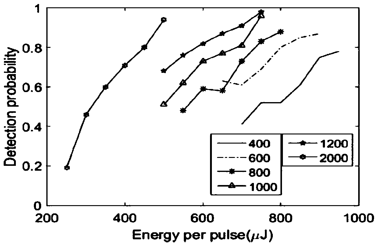
[0081] 64×64Gm-APD is used to realize laser detection, the field of view is 2°×2°, the receiving aperture is 65mm, the transmittance of the transmitting and receiving optics is 0.9, the duty cycle of the detector is 15%, the quantum efficiency of the detector is 10%, and the laser The wave band is 1064nm, the laser pulse width is 2.5ns, the time accuracy of Gm-APD is 1.25ns, the daytime noise is 13MHz, the detector noise is ignored, the target reflectivity is 0.1, and the detection distance is 5km. figure 2 It is the detection probability curve corresponding to different statistics and laser emission energy. Table 1 shows the laser single pulse energy corresponding to different frame numbers to achieve 5km detection, the detection probability reaches 70%. From the results of theoretical demonstration, when the number of statistical frames is fixed, the higher the single pulse energy is, the greater the detection probability is. When the detection probability is fixed, the larg...


PUM


Abstract

The invention discloses a method for calculating the farthest detection distance of a Gm-APD laser radar. The method comprises the following steps: 1, acquiring echo intensity by using a laser radar equation; 2, obtaining the triggering probability of each time interval of the Gm-APD laser radar; 3, acquiring simulation data under different statistical frame number conditions by using a Monte Carlo method; 4, echo parameters are obtained through a signal detection method according to the Gm-APD trigger probability curve obtained in the step 2 and the simulation data obtained in the step 3; and5, calculating echo detection probability and confirming optimal parameters of the system. The Gm-APD performs optimal argumentation on parameters such as laser parameters and optical aperture underthe condition that the index parameters are determined, so that the laser radar system realizes optimal power consumption and volume on the premise of meeting the indexes, and has a very important promotion effect on further engineering of the Gm-APD laser radar.

Description

technical field [0001] The invention belongs to the technical field of laser radar; in particular, it relates to a calculation method for the farthest detection distance of a Gm-APD laser radar. Background technique [0002] Gm-APD laser active detection technology has been developed for more than 20 years, and its engineering application is becoming more and more mature. lacking. The farthest detection distance of the target is one of the most important indicators of laser radar. According to the existing research results, when the indicator is determined, there is no effective theory for each parameter in the design process, such as laser single pulse energy, cumulative The number of frames, optical aperture, etc. are strictly theoretically demonstrated. In order to ensure the indicators in the actual construction process, parameters such as high laser single pulse energy and large optical aperture are often selected, resulting in an increase in actual volume and power co...

Claims


Application Information

Patent Timeline
IPC IPC(8): G06F30/20G01S7/497G06F111/06
CPCG01S7/497
Inventor 孙剑峰周鑫刘迪王骐
Owner HARBIN INST OF TECH
Learn More