
Discrete combined optical bench

An optical bench and combined technology, applied in the direction of educational appliances, instruments, teaching models, etc., can solve the problems of difficult handling and storage, large reading error, long length, etc., and achieve easy handling and storage, convenient operation, and short length Effect

Pending Publication Date: 2020-04-28
NORTHEAST GASOLINEEUM UNIV
View PDF0 Cites 0 Cited by
  • Summary
  • Abstract
  • Description
  • Claims
  • Application Information

AI Technical Summary

Problems solved by technology

From the point of view of use, these optical benches have the disadvantages of heavy weight, long length, difficult to carry and store, reading the position of the optical bench according to the scale, and large reading errors.

Method used


Image

  • Discrete combined optical bench

Examples


Embodiment 1

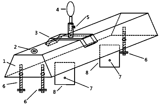
[0013] refer to figure 1 , a discrete combined optical bench, the optical bench includes an optical bench guide rail 1, an optical bench 4 and a horizontal adjustment screw 6; the optical bench 4 is inserted into the sleeve of the optical bench slider 3, and passed through The set screw 5 is locked and fixed, the optical bench slider 3 is slidably installed on the optical bench rail 1, and the top of the optical bench rail 1 is provided with a circular level bubble 2; the horizontal adjustment screw 6 is installed on the optical bench The bottom of the guide rail 1; the optical bench also includes two baffle plates 8 and a laser rangefinder fixed on the bottom surface of the optical bench guide rail 1, the two baffle plates 8 are respectively provided with light-through small holes 7, and the two through-holes The optical small hole 7 is on the same central axis, and the central axis is parallel to the top surface of the optical bench guide rail 1; the laser range finder is ar...


PUM


Abstract

The invention belongs to the technical field of physical experiment equipment, and particularly relates to a discrete combined optical bench which comprises an optical bench guide rail, an optical bench and a horizontal adjusting screw. An optical bench is inserted in a sleeve of the optical bench slide block, the optical bench slide block is slidably installed on the optical bench guide rail, andthe top end of the optical bench guide rail is provided with a circular level bubble. The horizontal adjusting screw is mounted at the bottom of the optical bench guide rail. The optical bench also comprises two baffle plates and a laser range finder which are fixed on the bottom surface of the optical bench guide rail. The two baffle plates are respectively provided with a small light through hole, the two small light through holes are arranged on the same central shaft, and the central shaft is parallel to the top surface of the optical bench guide rail. The laser range finder is arranged on one side of the two baffle plates. According to the combined optical bench, the discrete optical bench bodies are coaxially adjusted through the laser range finders, and the combined optical bench has the characteristics of a traditional optical bench and also has the characteristics of being short in length, light in weight, easy to store, transport and store and capable of being combined at will.

Description

Technical field: [0001] The invention belongs to the technical field of physical experiment equipment, and in particular relates to a discrete combined optical bench. Background technique: [0002] Optical benches are indispensable equipment for optical experiments in universities, middle schools, primary schools, and scientific research units. At present, most of the optical benches used by people are made of cast iron or other dense materials, and they are relatively long. Put the optical instruments on the optical bench for relative position adjustment, and read according to the attached scale on the optical bench to determine the relative position of each optical bench. From the perspective of use, these optical benches have the disadvantages of heavy weight, long length, difficult handling and storage, and large reading errors when reading the position of the optical bench according to the scale. Therefore, it is very necessary to design a discrete combined optical ben...

Claims


Application Information

Patent Timeline
Patent Type & Authority Applications(China)
IPC IPC(8): G09B23/22
CPCG09B23/22
Inventor 董向国白永强
Owner NORTHEAST GASOLINEEUM UNIV
Learn More